Supercharge Your Innovation With Domain-Expert AI Agents!

Positioning tool for injection molding ball valve

A technology for positioning tooling and ball valves, applied in the direction of coating, etc., can solve the problems of ball valve production quality, impact on ball valve control sealing effect, valve core pressure loss, etc.

Pending Publication Date: 2022-07-22
YONGGAO CO LTD
View PDF1 Cites 0 Cited by
  • Summary
  • Abstract
  • Description
  • Claims
  • Application Information

AI Technical Summary

Problems solved by technology

[0004] The tooling in the above structure can realize the positioning operation of the mold rod and the ball valve or the valve core. The structure of the tooling is fixed, and the valve core can be kept at the reference height against the supporting surface on the tooling. After the injection molding of the ball valve is completed, the valve core is maintained In order to make the core of the mold stem smoothly, it is necessary to apply force so that the port of the ball valve is supported on the step surface at a specified distance below the supporting surface of the tooling at the same time. However, due to the heat and cooling of the ball valve after injection molding, its size will change to a certain extent. When the ball valve When pressing down and positioning on the tooling, the end surface of the ball valve may not be in contact with the step surface, but the valve core is already in contact with the supporting surface. At this time, the force is concentrated on the valve core with a smaller contact area, which may cause pressure loss on the valve core. , the valve core is a rotating part inside the ball valve, which directly affects the control and sealing effect inside the ball valve, which will affect the production quality of the ball valve

Method used


Image

  • Positioning tool for injection molding ball valve
  • Positioning tool for injection molding ball valve
  • Positioning tool for injection molding ball valve

Examples


Embodiment Construction

[0028] The following are specific embodiments of the present invention and the accompanying drawings to further describe the technical solutions of the present invention, but the present invention is not limited to these embodiments.

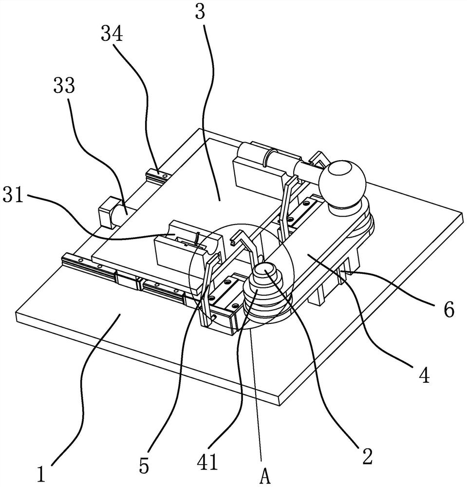
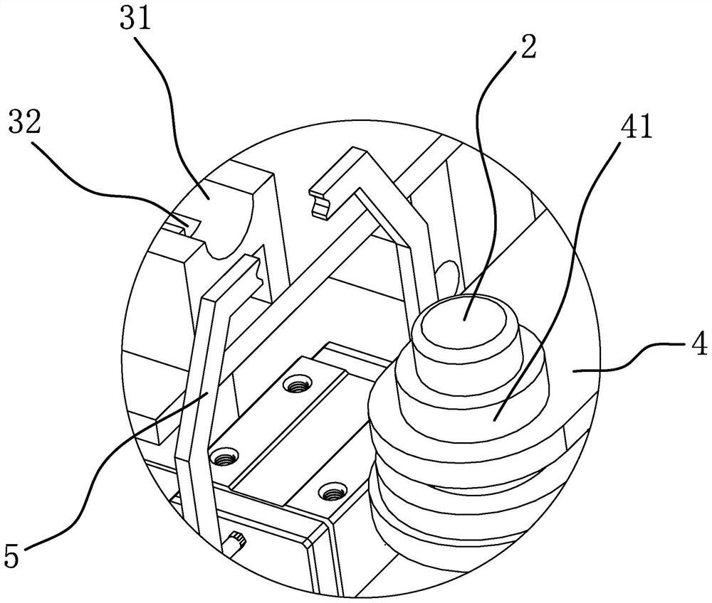
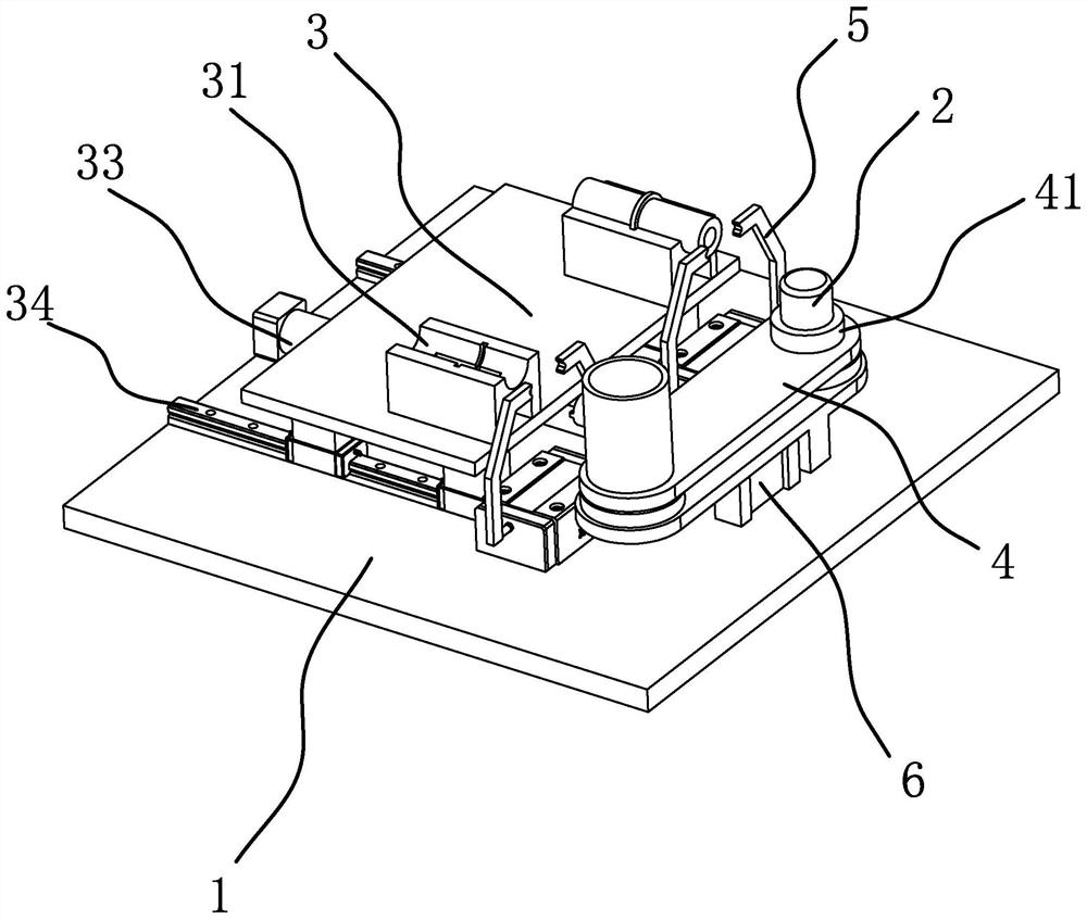
[0029] like Figure 1-3As shown, the positioning tooling of the injection ball valve includes a support platform 1, and the support platform 1 is connected with a positioning column 2 for positioning and matching with the inner hole of the valve core and a movable seat 3 for horizontally positioning the mold rod 8. The positioning column 2 is vertical The movable seat 3 can drive the mold rod to reciprocate along the axial direction of the mold rod toward the positioning column 2. The outer peripheral surface of the positioning column 2 is sleeved with a support sleeve 4 that can be positioned with the inner diameter of the formed ball valve port. Reciprocating vertically along the positioning column 2, the top surface of the support sleeve 4 ha...


PUM


Abstract

The invention provides a positioning tool for an injection molding ball valve, and belongs to the technical field of ball valve production equipment. The technical problem that an existing injection molding ball valve positioning tool affects the production quality is solved. The positioning tool for the injection molding ball valve comprises a supporting platform, a positioning column used for being in positioning fit with an inner hole of a valve element and a moving seat used for positioning a horizontal mold rod are connected to the supporting platform, the positioning column is vertically arranged, and the moving seat can drive the mold rod to reciprocate towards the positioning column in the axial direction of the mold rod. The peripheral face of the positioning column is sleeved with a supporting sleeve capable of vertically moving in a reciprocating mode along the positioning column, the top face of the supporting sleeve is provided with an annular boss, the peripheral face of the annular boss can be matched with the inner edge of a ball valve port, and when only the valve element is arranged on the positioning column in a sleeving mode, the valve element can abut against the top face of the annular boss and is opposite to a die rod positioned on the movable base in the horizontal direction. The supporting sleeve can move downwards so that when the ball valve can be arranged on the periphery of the annular boss in a sleeving mode, the die rod on the ball valve can abut against and be located on the movable base from top to bottom. The quality of the injection molding ball valve can be guaranteed.

Description

technical field [0001] The invention belongs to the technical field of ball valve production equipment, and relates to a positioning tool for an injection ball valve. Background technique [0002] Plastic ball valves are widely used in more and more industries. During the processing of plastic ball valves, the mold stem, valve core and valve core sealing ring are pre-installed in the injection molding mold of the valve body as inserts. As a whole, the mold rod is finally separated from the ball valve. The ball valve formed in this way has a stable structure and higher working stability. The valve core has a valve rod and an inner hole for water supply, and the inner diameter of the inner hole is smaller than that of the ball valve port. . [0003] The Chinese patent application publication number CN110227942A discloses an assembly machine including a workbench, a sealing ring feeding device, a valve core feeding device, an injection mold, a manipulator and a valve core inse...

Claims


Application Information

Patent Timeline
IPC IPC(8): B29C45/14B29C45/17
CPCB29C45/14819B29C45/17B29C45/1756
Inventor 孙华丽陈卫郦伟波王超峰李海超贺晓莉
Owner YONGGAO CO LTD
Features
  • R&D
  • Intellectual Property
  • Life Sciences
  • Materials
  • Tech Scout
  • Unparalleled Data Quality
  • Higher Quality Content
  • 60% Fewer Hallucinations
Learn More