Tire thermocuring flow production line

A thermal curing and production line technology, which is applied to tires, household appliances, and other household appliances, can solve the problems of air pollution in production areas, inability to guarantee product consistency, and heat loss in tanks, so as to ensure thermal curing time and avoid Effect of heat dissipation and improvement of production efficiency

Pending Publication Date: 2022-07-22
HUAIYIN INSTITUTE OF TECHNOLOGY
View PDF1 Cites 0 Cited by
  • Summary
  • Abstract
  • Description
  • Claims
  • Application Information

AI Technical Summary

Problems solved by technology

However, the above-mentioned equipment is a tank-shaped structure, that is to say, it can only enter the tanks one by one to realize thermal curing during production, which leads to a large amount of heat in the tank body every time the tank door is opened during the production process. Loss, resulting in the need to raise the temperature in the tank to the temperature required for heat curing again when it is used again, the required energy consumption is large, the production time is long each time, the production efficiency is low, and the waste gas in the tank will also be opened after opening Exposure to the production workshop, causing pollution to the air environment in the production area
Moreover, the one-time thermal curing effect of tires produced in different batches will be different, and the consistency of the product cannot be guaranteed

Method used


Image

  • Tire thermocuring flow production line
  • Tire thermocuring flow production line
  • Tire thermocuring flow production line

Examples


Embodiment Construction

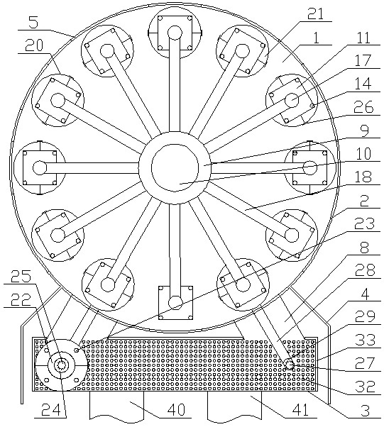
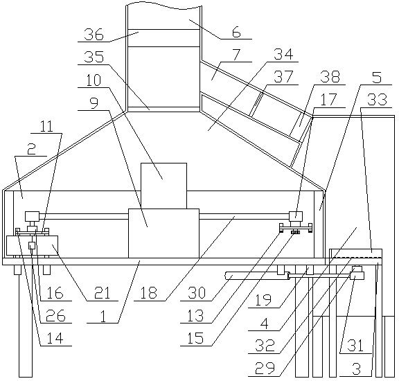
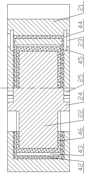
[0035] combine Figure 1~Figure 3 It can be seen that the thermal curing production line for tires includes a work station 1. The center of the top surface of the work station 1 is provided with a vertical shaft. The top of the vertical shaft is fixedly connected with a station rotating motor 10. The output shaft of the rotating motor 10 is fixedly connected with the rotating shaft sleeve 9 which is horizontally rotated around the axis of the vertical shaft and is sleeved on the outer side wall of the vertical shaft. The outer side wall of the rotating shaft sleeve 9 is fixedly connected with a plurality of connecting rods 18. 18 is evenly distributed with the axis of the vertical shaft as the center, one end of the connecting rod 18 away from the rotating shaft sleeve 9 is fixedly connected with a lifting device A17, and the bottom of the lifting device A17 is connected with an epicyclic plate 11 for the epicyclic tire heat curing mold 20 The bottom of the turntable 11 is pro...


PUM


Abstract

A station rotating motor is fixed to a vertical shaft in the center of a station table, an output shaft is fixed to a rotating shaft sleeve, a connecting rod is fixed to the rotating shaft sleeve, a lifting device A is fixed to the connecting rod, a turnover plate is arranged at the bottom of the lifting device A, and a grabbing device is arranged at the bottom of the turnover plate; the grabbing device moves downwards to the maximum stroke, fixes the tire thermocuring mold and is connected with the electric heating device, the grabbing device moves upwards to the maximum stroke, the grabbing device is separated from the tire thermocuring mold, each station is provided with a positioning device, a heat preservation cover is fixed to the upper portion of the station table, and an operation table is arranged on one side of the station table. The two ends, facing the station table, of the operation table are connected with the station table through connecting tables, and a tire feeding frame and a tire discharging frame are arranged on one side of the operation table. Known from the structure, the thermocuring flow production line of the tire realizes continuous production of one-time thermocuring molding of the tire using a composite fiber material as a belted layer, and the production efficiency is improved.

Description

technical field [0001] The invention relates to the technical field of a tire thermal curing molding equipment assembly line, in particular to a tire thermal curing assembly line. Background technique [0002] Car tires are one of the important parts of the car. They are in direct contact with the road surface, and together with the car suspension, they can alleviate the impact of the car while driving, so as to ensure the car has good ride comfort and ride comfort; Good adhesion; improve the traction, braking and passability of the car; bear the weight of the car, the important role of the tire on the car is more and more people's attention. [0003] Polyacrylonitrile carbon fiber needs to be thermally cured to achieve the properties of the above-mentioned polyacrylonitrile carbon fiber; the study found that the temperature range of the thermal curing process of polyacrylonitrile carbon fiber is similar to the temperature range of tire vulcanization, and there are overlappi...

Claims


Application Information

Patent Timeline
IPC IPC(8): B29D30/06
CPCB29D30/0601B29D30/0603B29D30/0606B29D2030/0607
Inventor 程杰汪通悦许兆美蒋志鹏王声超蔡玉强杨清清
Owner HUAIYIN INSTITUTE OF TECHNOLOGY
Why Eureka
Try Eureka