
Thermal management system of electric automobile

A thermal management system and technology for electric vehicles, applied in the field of thermal management systems for electric vehicles, can solve problems such as interconnection and poor control of motor thermal management, and incomplete functional scenarios of thermal management systems, achieving low cost, easy control, and simple control. Effect

Pending Publication Date: 2022-07-22
SOUTH AIR INT
View PDF0 Cites 1 Cited by
  • Summary
  • Abstract
  • Description
  • Claims
  • Application Information

AI Technical Summary

Problems solved by technology

At present, the functional scenarios of the electric vehicle thermal management system are not comprehensive, and the balance between the mileage, comfort and safety of the electric vehicle in the actual environment cannot be well achieved, mainly in the passenger compartment thermal management, battery thermal management, motor The three aspects of thermal management are interconnected and poorly controlled

Method used


Image

  • Thermal management system of electric automobile

Examples


Embodiment 1

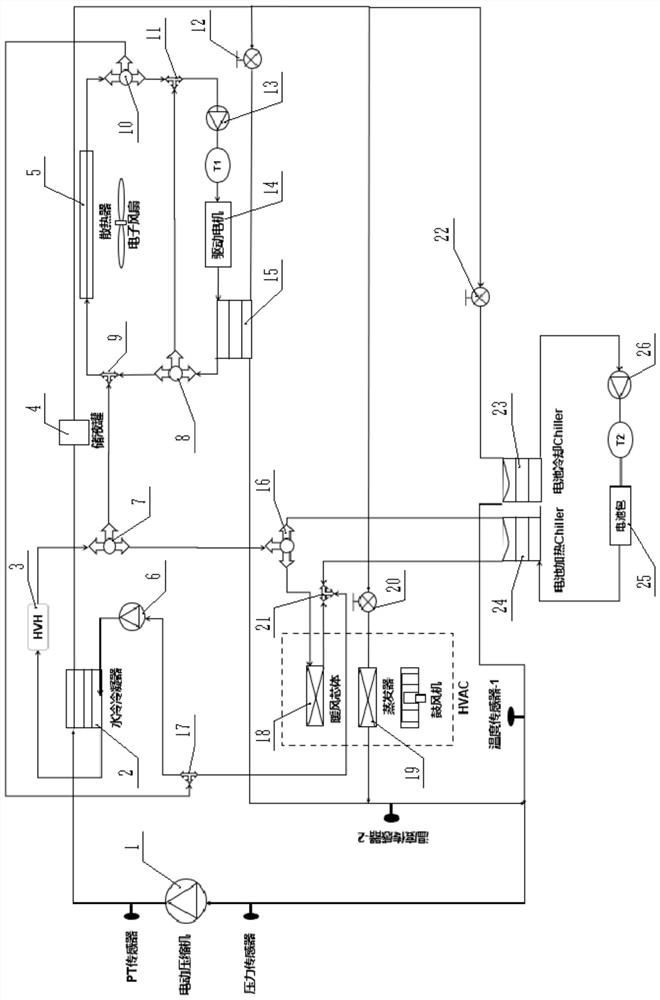
[0068] see figure 1 , is an electric vehicle thermal management system, including a refrigerant circuit, a battery circuit, a motor circuit, and a warm air circuit; the refrigerant circuit is provided with a refrigerant, and the battery circuit, the motor circuit, and the warm air circuit are all provided with cooling liquid;

[0069] The refrigerant circuit includes an electric compressor 1, a water-cooled condenser 2, a liquid storage tank 4, an evaporator 19, a battery cooling Chiller 23, a waste heat recovery device 15, a first EXV electronic expansion valve 12, a second EXV electronic expansion valve 20, and a third EXV Electronic expansion valve 22; the refrigerant circuit includes a first refrigerant circuit, a second refrigerant circuit, and a third refrigerant circuit;

[0070] The first refrigerant circuit includes an electric compressor 1, a water-cooled condenser 2, a liquid storage tank 4, a second EXV electronic expansion valve 20, and an evaporator 19, which are...

Embodiment 2

[0110] The difference between this embodiment and Embodiment 1 is that: on the basis of Embodiment 1, a high-voltage electric heater HVH3 is added to the heating air circuit, and the high-voltage electric heater HVH3 is installed on the water-cooled condenser 2 and the first three-way valve. On the connecting pipeline between 7, it is used to heat the coolant in the heating circuit.

[0111] The passenger compartment thermal management also includes a passenger compartment HVH compensated heating mode, and the battery thermal management also includes a battery HVH compensated heating mode.

[0112] The working mode of the HVH compensation heating mode of the passenger compartment is: open the first heating air circuit in the heating air circuit;

[0113] The cooling liquid circulates in the first warm air circuit; after the cooling liquid is compensated and heated by the high-voltage electric heater HVH3, the passenger compartment is heated by the warm air core 18.

[0114] T...


PUM


Abstract

The invention belongs to the technical field of automobile heat management, and relates to an electric automobile heat management system which comprises a refrigerant loop, a battery loop, a warm air loop and a motor loop. Refrigerant is arranged in the refrigerant loop, and cooling liquid is arranged in the battery loop, the warm air loop and the motor loop. According to the electric vehicle heat management system, through mutual correlation coupling of the refrigerant loop, the warm air loop, the battery loop and the motor loop, waste heat of the motor and the like is fully utilized, independent or mutual correlation operation of passenger compartment heat management, battery heat management and motor heat management in different functional scenes can be achieved, and the cooling and heating function requirements of the heat management system are met. The thermal management system is comprehensive in function scene, low in cost, simple in system and convenient to control. Passenger compartment heating and battery heating share one high-voltage electric heater HVH, the air conditioning box can be completely shared by a fuel vehicle and a new energy vehicle, and platformization is easy to achieve.

Description

technical field [0001] The invention belongs to the technical field of automobile thermal management, and relates to an electric vehicle thermal management system. Background technique [0002] For electric vehicles, the thermal management system not only affects the driving comfort of passenger vehicles, but also involves safety and energy consumption issues. How to achieve the balance between driving range, comfort and safety in the actual environment of electric vehicles Balance is an urgent problem to be solved in the design of electric vehicle thermal management system. At present, the functional scenarios of the thermal management system for electric vehicles are not comprehensive, and the balance between the driving range, comfort and safety of electric vehicles in the actual environment cannot be well achieved. The three aspects of thermal management are poorly interconnected and poorly controlled. SUMMARY OF THE INVENTION [0003] In view of this, the present in...

Claims


Application Information

Patent Timeline
Patent Type & Authority Applications(China)
IPC IPC(8): B60H1/00B60H1/14B60H1/22B60H1/32
CPCB60H1/00028B60H1/00278B60H1/00392B60H1/143B60H1/2215B60H1/3227B60H1/3228B60H1/00485
Inventor 王洪强张继鑫覃旗开张瑞江澜王鑫
Owner SOUTH AIR INT
Learn More