Supercharge Your Innovation With Domain-Expert AI Agents!

Fiber cloth strip feeding system suitable for weft laying machine

A feeding system and cloth strip technology, applied in the direction of thin material processing, winding strips, sending objects, etc., can solve the problems of inconvenient application operation, unfavorable popularization, promotion, high requirements for worker quality and work responsibility, and achieve The effect of low manufacturing cost, preventing being torn off, and simple design structure

Pending Publication Date: 2022-07-22
CHANGZHOU WUJIN WUYANG TEXTILE MACHINERY
View PDF2 Cites 0 Cited by
  • Summary
  • Abstract
  • Description
  • Claims
  • Application Information

AI Technical Summary

Problems solved by technology

Through the application of the above technical solutions, although it can effectively ensure that the yarn in the feeding process is always kept in a reasonable tension state, when the tension of the yarn needs to be adjusted, it is necessary to frequently rotate the screw to increase the tension. Raising or lowering the relative height position of the tensioning wheel is extremely inconvenient for application and operation, and the rotation and operation of the screw completely depends on the experience of the workers, which requires high quality of workers and work responsibility, which is not conducive to popularization and promotion

Method used


Image

  • Fiber cloth strip feeding system suitable for weft laying machine
  • Fiber cloth strip feeding system suitable for weft laying machine
  • Fiber cloth strip feeding system suitable for weft laying machine

Examples


Embodiment Construction

[0043] In the description of the present invention, it should be understood that the orientation or positional relationship indicated by the terms "front", "rear", "upper", "lower", "left", "right", etc. are based on those shown in the accompanying drawings The orientation or positional relationship is only for the convenience of describing the present invention and simplifying the description, rather than indicating or implying that the referred device or element must have a specific orientation, be constructed and operated in a specific orientation, and therefore should not be construed as a limitation of the present invention.

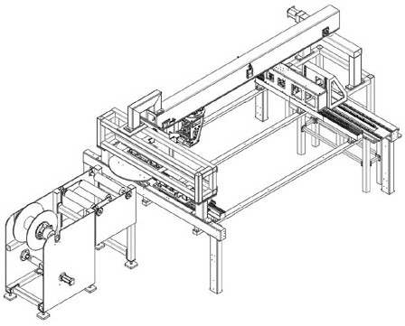
[0044] figure 1 The schematic diagram of the actual application state of the fiber cloth sliver feeding system suitable for the weft laying machine in the present invention is shown. It can be seen that the weft laying machine used for weaving fiber cloth mainly consists of a fiber cloth sliver feeding system, a left feeding mechanism, It consists o...


PUM


Abstract

The invention relates to a fiber cloth strip feeding system suitable for a weft laying machine. The fiber cloth strip feeding system comprises an unwinding device and a tensioning device. A fiber cloth strip is flattened and sent out through the unwinding device and then sequentially passes through the rotating roller assembly, the gravity roller assembly and the guide roller assembly in a winding mode. In the feeding process of a fiber cloth strip, the rotating roller assembly, the gravity roller assembly and the guide roller assembly always perform circumferential rotating motion around the central axis of the fiber cloth strip under the action of the friction force of the fiber cloth strip, and the gravity roller assembly tensions the fiber cloth strip under the action of the gravity of the gravity roller assembly. Therefore, the fiber cloth strip is always kept in a reasonable tensioning state, the fiber cloth strip can be continuously and stably fed into the weft laying machine, and the weft laying process can be smoothly implemented. In addition, the deflection angle of the gravity roller assembly can also be adaptively changed along with the change of the feeding speed of the fiber cloth strip, so that the phenomenon that the gravity roller assembly is snapped due to the action of overlarge tension is avoided.

Description

technical field [0001] The invention relates to the technical field of textile machinery and equipment manufacturing, in particular to a fiber cloth strip feeding system suitable for a weft laying machine. Background technique [0002] Carbon fiber is a new type of material with a carbon content of more than 95%, with high strength and high modulus. Carbon fiber is composed of organic fibers such as flake graphite microcrystals stacked along the fiber axial direction. The microcrystalline graphite material obtained by carbonization and graphitization not only has the inherent intrinsic properties of carbon materials, but also has the softness of textile fibers. machinability. [0003] The fiber cloth is woven from carbon fiber, and its production process is roughly as follows: flatten the carbon fiber bundle into a flat monofilament carbon fiber through a yarn spreader, and then bond it into a fiber cloth strip with glue, and then spread it by laying The weft machine is us...

Claims


Application Information

Patent Timeline
Patent Type & Authority Applications(China)
IPC IPC(8): B65H18/10B65H41/00B65H23/26B65H23/00B65H16/02
CPCB65H18/103B65H23/26B65H23/00B65H16/02B65H41/00B65H2701/174
Inventor 王菡珠恽一飞白奕巍杨曜华
Owner CHANGZHOU WUJIN WUYANG TEXTILE MACHINERY
Features
  • R&D
  • Intellectual Property
  • Life Sciences
  • Materials
  • Tech Scout
  • Unparalleled Data Quality
  • Higher Quality Content
  • 60% Fewer Hallucinations
Learn More