Limiting self-resetting railway swing hollow pier with built-in corrugated web dampers

A corrugated web and damper technology, used in bridges, bridge construction, bridge parts, etc., can solve problems such as poor energy dissipation capacity, prone to man-made damage, affecting service life, etc., and achieve the effect of improving shear resistance.

Pending Publication Date: 2022-07-22
CENT SOUTH UNIV
View PDF0 Cites 0 Cited by
  • Summary
  • Abstract
  • Description
  • Claims
  • Application Information

AI Technical Summary

Problems solved by technology

However, the energy consumption capacity of the swaying bridge pier is poor during earthquakes, and it is often necessary to install an additional damper during swaying, and the damper is installed externally. The external damper is not only prone to man-made damage, but also affected by environmental factors. Service life

Method used


Image

  • Limiting self-resetting railway swing hollow pier with built-in corrugated web dampers
  • Limiting self-resetting railway swing hollow pier with built-in corrugated web dampers
  • Limiting self-resetting railway swing hollow pier with built-in corrugated web dampers

Examples


Embodiment 1

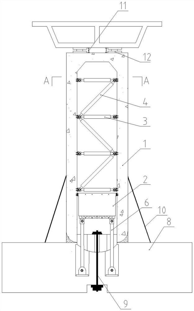
[0024] Example one, as figure 1 As shown in the figure, the limit self-resetting railway swing hollow pier with built-in corrugated web damper disclosed in this embodiment mainly includes a hollow pier body 1, a corrugated web damper 2, a horizontal strut 3, a diagonal strut 4, Mounting seat 5 , tie rod 6 , fiber concrete support seat 7 , cast-in-place foundation 8 , unbonded prestressed steel bar 9 , steel strand 10 , damping tenon 11 and rubber bearing 12 .

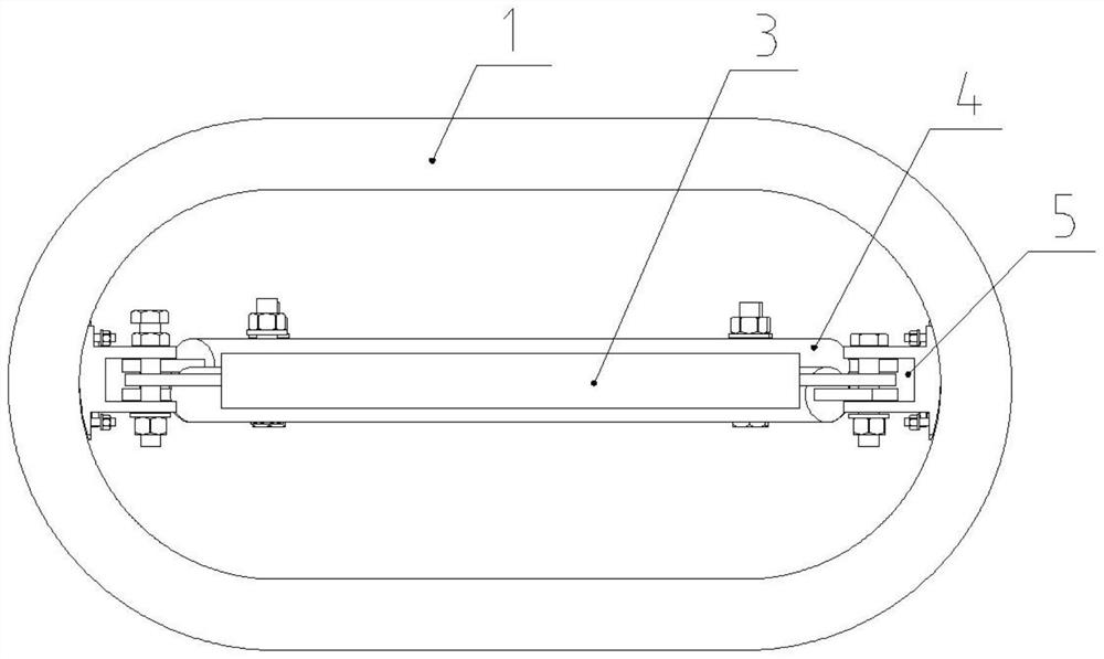
[0025] After combining figure 1 , figure 2 It can be seen that the two ends of the transverse bridge of the hollow pier body 1 are round ends, and the transverse bridge in the inner cavity is fixed with a corrugated web damper 2 toward the bottom of the central plane. The strut 3, the diagonal strut 4 and the mounting seat 5 are assembled by fasteners.

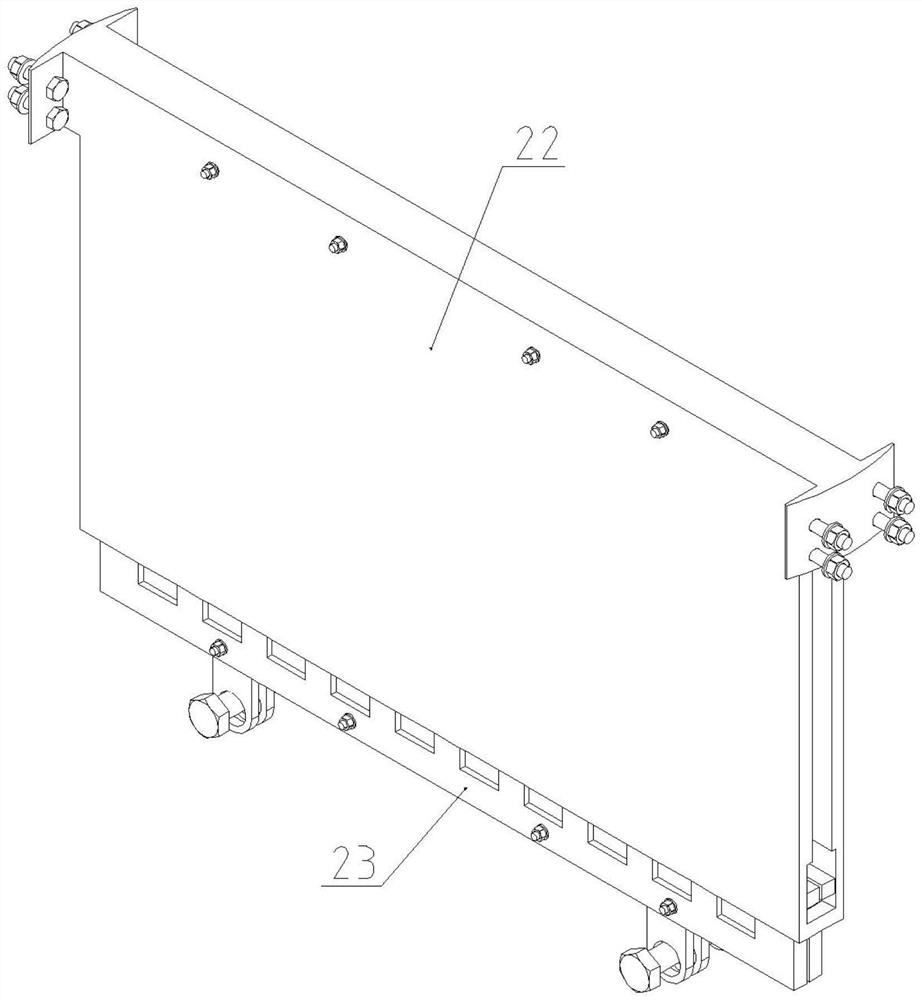
[0026] After combining figure 2 , image 3 It can be seen that the corrugated web damper 2 includes a corrugated web 21 , a mounting box 22 and a clamping plate ...

Embodiment 2

[0063] The second embodiment, the main difference between this embodiment and the first embodiment is that the structure of the built-in corrugated web damper at the bottom of the pier is different. The corrugated web damper 2 of this embodiment includes a corrugated web 21 and an installation frame 24. The installation frame 24 is an inverted U-shaped frame with a circle of rectangular grooves on its inner wall, and the lower ends of the rectangular groove segments on the arms on both sides are blind ends , so that the corrugated web can be down-limited to prevent the corrugated web 21 from being pulled out of the mounting frame 24, the width of the rectangular groove is greater than the total thickness of the corrugated section of the corrugated web 21, the corrugation of the corrugated web 21 Two side-by-side corrugated webs are placed in a rectangular groove, and the top is suspended by bolts penetrating the mounting frame 24; the upper end of the mounting frame is symmetri...


PUM


Abstract

The invention discloses a limiting self-resetting railway swing hollow pier with a built-in corrugated web damper, the bottom of a round-end-shaped hollow pier body is assembled with a mounting foundation in an embedded manner, the bottom of an inner cavity of the hollow pier body is provided with the corrugated web damper along the transverse direction of the hollow pier body, and the lower end of the corrugated web damper is hinged with the foundation through a pull rod. When the pier swings, the corrugated web dampers consume energy to reduce input of earthquake energy, the supporting rod assemblies are arranged over the corrugated web dampers, and the shear capacity and integrity of the pier can be improved; the unbonded prestressed steel bars are anchored between the axial center of the pier bottom and the foundation, so that the pier can be lifted and swung under the action of an earthquake to avoid damage to the pier body structure, the swing amplitude is limited to a certain degree, and the pier has a certain post-earthquake self-resetting function. The arrangement of the corrugated web dampers can also improve the shear capacity of the pier to a certain extent.

Description

technical field [0001] The invention belongs to the seismic field of bridge engineering, in particular to a limit self-resetting railway swing hollow pier with a built-in corrugated web damper. Background technique [0002] Bridges occupy a huge proportion in high-speed railways, making their importance in rail transportation irreplaceable. The current seismic design of bridges is mainly based on the concept of ductile seismic resistance, which dissipates seismic energy by setting plastic hinges to generate plastic deformation. However, this design method will generate large residual displacement after the earthquake, and is prone to local severe damage. For bridges with structural damage, they can only be repaired by demolition and reconstruction, which causes great economic losses and lags the speed of repair. [0003] After the earthquake, the damaged bridges not only lost the ability of rail transportation, but also seriously delayed the network transportation, which b...

Claims


Application Information

Patent Timeline
IPC IPC(8): E01D19/02E01D2/04E01D19/00E04H9/02
CPCE01D19/02E01D2/04E01D19/00E04H9/021E04H9/0237
Inventor 周旺保王晓婵娟蒋丽忠彭东航聂磊鑫任振彬
Owner CENT SOUTH UNIV
Why Eureka
Try Eureka