
Novel sponge city rainwater treatment system

A technology of sponge city and treatment system, applied in the field of new sponge city rainwater treatment system, can solve the problems of inability to change the amount of infiltration, insufficient urban irrigation, insufficient infiltration capacity, etc., achieve better cleaning effect, and prevent a large amount of water accumulation and infiltration. small amount of effect

Pending Publication Date: 2022-07-22
RES CENT FOR ECO ENVIRONMENTAL SCI THE CHINESE ACAD OF SCI
View PDF0 Cites 0 Cited by
  • Summary
  • Abstract
  • Description
  • Claims
  • Application Information

AI Technical Summary

Problems solved by technology

[0003] However, the existing sponge city system cannot change the amount of infiltration when the precipitation is different. The infiltration capacity is insufficient when the rainfall is large, which will easily lead to serious urban waterlogging. Designing a sponge city rainwater treatment system that can collect and treat rainwater according to different precipitation amounts is of great significance to the construction of sponge cities

Method used


Image

  • Novel sponge city rainwater treatment system
  • Novel sponge city rainwater treatment system
  • Novel sponge city rainwater treatment system

Examples


Embodiment 1

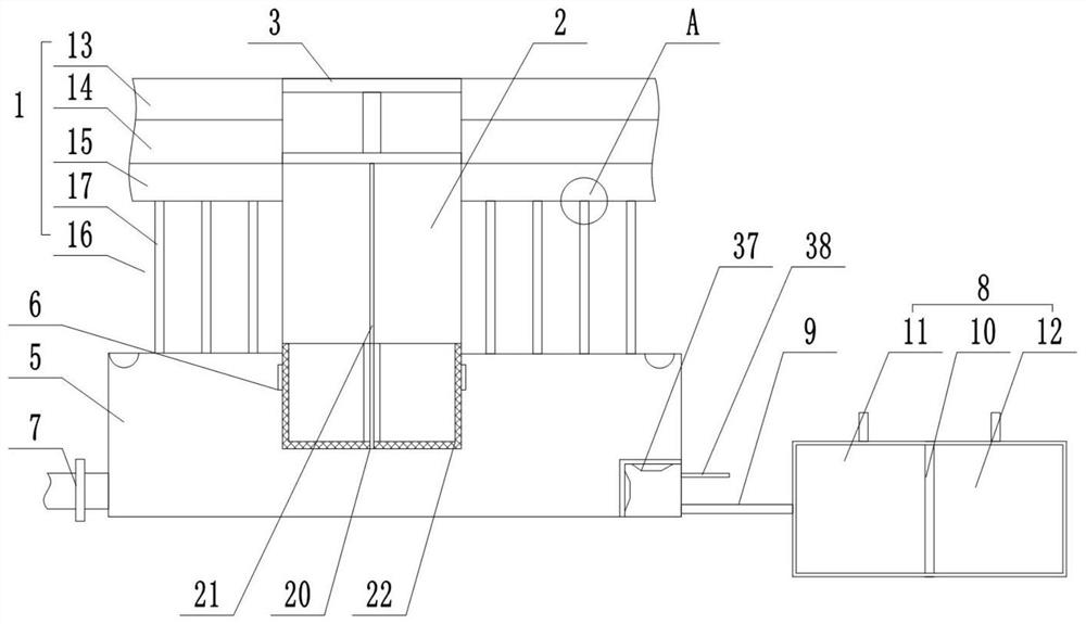
[0033] refer to Figure 1-6 , this embodiment provides a new type of sponge city rainwater treatment system, including:

[0034] ground floor 1;

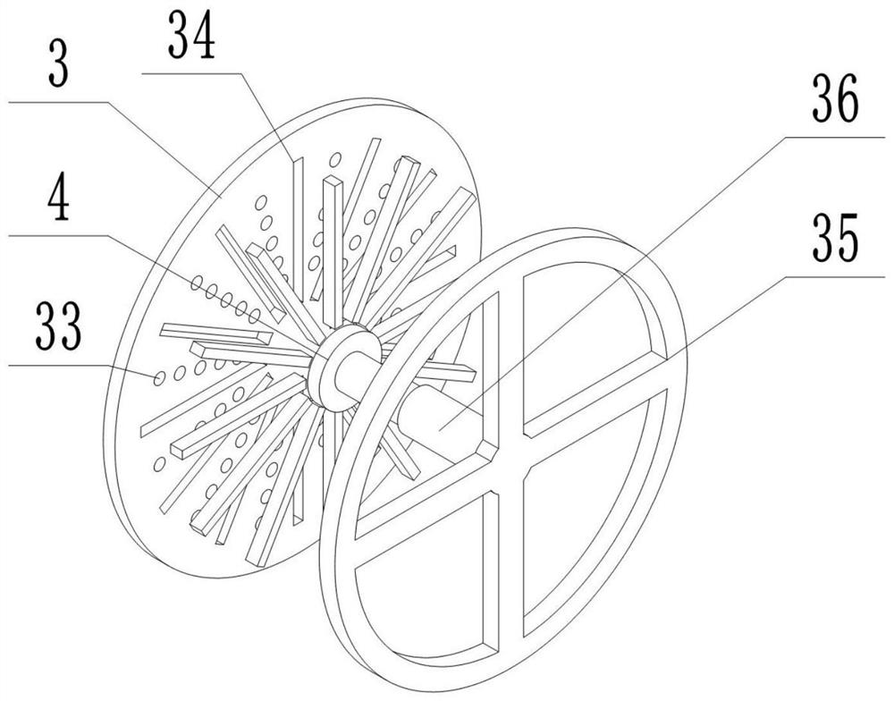
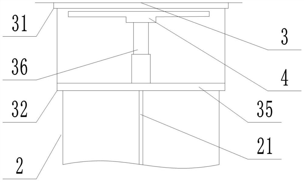
[0035] The seepage well 2 is embedded in the ground layer 1; the seepage well 2 is slidably connected with a coarse filter assembly; the inlet of the seepage well 2 is provided with a wellhead assembly; the wellhead assembly comprises a fixed plate 3 embedded in the wellhead of the seepage well 2 , a lifting plate 4 is detachably connected in the fixing plate 3, and a supporting component is fixedly connected to the bottom end of the lifting plate 4, and the supporting component is fixedly installed in the seepage well 2;

[0036] Water storage cavity 5, the water storage cavity 5 is arranged under the ground layer 1, and the ground layer 1 and the seepage well 2 are respectively connected with the water storage cavity 5; The side wall of 2 is communicated with the water storage cavity 5 through several circumferentially arranged ...

Embodiment 2

[0056] According to the attached Figure 7-8 The difference between this embodiment and the first embodiment is that the multiplexing pipe 9 is provided with an anti-blocking mechanism, which is used to reduce the blocking probability of the multiplexing pipe 9 .

[0057] The anti-blocking mechanism includes an active runner 39, a driven runner 40 and an oscillating device. Both the active runner 39 and the driven runner 40 are rotatably connected to the inner wall of the multiplexing pipe 9, and the active runner 39 and the driven runner 40 are driven connected, the driven runner 40 is connected with the oscillating assembly in a transmission; the water flow entering the multiplexing pipe 9 drives the active runner 39 to rotate, and the active runner 39 drives the driven runner 40 to rotate, and then drives the oscillating assembly to vibrate back and forth to prevent impurities from depositing, Cause the reuse pipe 9 to be blocked.

[0058] The driving wheel 39 includes a f...


PUM


Abstract

The invention discloses a novel sponge city rainwater treatment system which comprises a ground layer, a seepage well, a water storage cavity and a reuse cavity. The seepage well is embedded in the ground layer, and a rough filtration assembly is slidably connected in the seepage well; the well mouth assembly comprises a fixing plate embedded in a well mouth of the water seepage well, a lifting plate is detachably connected into the fixing plate, and a supporting assembly is fixedly connected to the bottom end of the lifting plate and fixedly installed in the water seepage well. The water storage cavity is arranged below the ground layer, the bottom end of the seepage well is communicated with the water storage cavity through a rough filtration assembly, and the side wall of the seepage well is communicated with the water storage cavity through a plurality of one-way valves arranged in the circumferential direction; the water storage cavity is provided with an emergency drain pipe; and the reuse cavity is communicated with the water storage cavity through a reuse pipe. The device has different infiltration capacities according to different precipitation amounts, the infiltration amount is small when the precipitation amount is small, part of rainfall can be intercepted, and the rainfall can irrigate cities. The cleaning effect is better; when the precipitation is large, the infiltration capacity is increased, a large amount of water is prevented from accumulating on the urban ground, and loss caused by waterlogging is reduced.

Description

technical field [0001] The invention relates to the technical field of sponge cities, in particular to a new type of rainwater treatment system for sponge cities. Background technique [0002] Sponge city is a new generation of urban stormwater management concept, which can also be called "water elastic city". The international term is "low-impact development of rainwater system construction", which absorbs water, stores water, seeps water, and purifies water when it rains, releases and utilizes the stored water when needed, and realizes the free migration of rainwater in the city. Building a sponge city, making overall use of natural ecological functions and artificial intervention functions, effectively controlling rainwater runoff, and realizing the urban development mode of natural accumulation, natural infiltration, and natural purification is conducive to restoring urban water ecology, conserving water resources, and enhancing urban waterlogging prevention capabilities...

Claims


Application Information

Patent Timeline
IPC IPC(8): E03F5/04E03F3/04E03F5/10E03F5/14E03F5/26
CPCE03F5/04E03F5/0401E03F5/0404E03F5/041E03F5/10E03F5/101E03F5/105E03F5/14E03F3/04E03F5/26Y02A20/108
Inventor 胡春明孙然好尤立
Owner RES CENT FOR ECO ENVIRONMENTAL SCI THE CHINESE ACAD OF SCI
Learn More