Thin film strain gauge bridge circuit based on flexible circuit board on high-rigidity force measuring knife handle

A flexible circuit board, bridge circuit technology, applied in the direction of measuring force, measuring device, measuring/indicating equipment, etc., can solve the problems of difficult to control thin film, resistance error, low resistance value, etc., to improve circuit stability, reduce Small wire length, reduced impact effect

Active Publication Date: 2022-07-22
UNIV OF ELECTRONICS SCI & TECH OF CHINA
View PDF18 Cites 0 Cited by
  • Summary
  • Abstract
  • Description
  • Claims
  • Application Information

AI Technical Summary

Problems solved by technology

Since the high-precision resistors on the market are generally standard resistors, the resistance value is not arbitrary. If two resistors R 3 with R 4 For registration, it is difficult to control the ratio of the resistance values ​​of the two registration resistors to be equal to the ratio of the resistance values ​​of the thin film strain resistance; and there are errors in the resistance, the higher the precision of the resistance, the higher the cost, and the fewer resistance values ​​​​to choose from

Method used


Image

  • Thin film strain gauge bridge circuit based on flexible circuit board on high-rigidity force measuring knife handle
  • Thin film strain gauge bridge circuit based on flexible circuit board on high-rigidity force measuring knife handle
  • Thin film strain gauge bridge circuit based on flexible circuit board on high-rigidity force measuring knife handle

Examples


Embodiment Construction

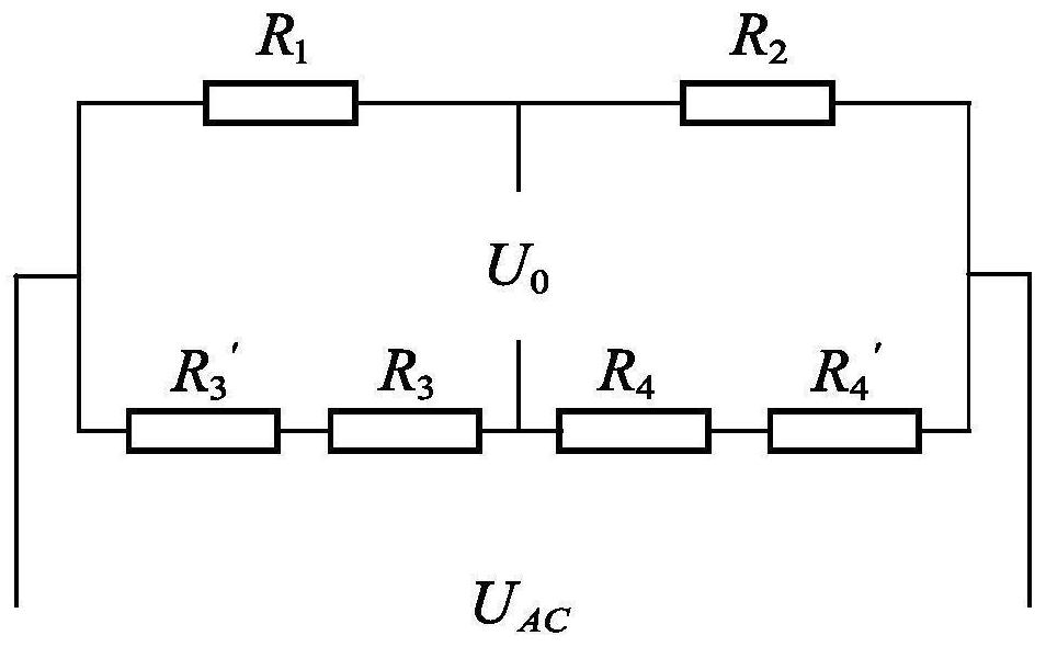
[0022] The technical solutions of the present invention are further described below with reference to the accompanying drawings.

[0023] like Figure 4 As shown in the figure, a thin-film strain gauge bridge circuit based on a flexible circuit board on a high-rigidity force measuring tool handle of the present invention adopts a structure of parallel registration of multi-stage resistances, including two thin-film strain resistances R 1 , R 2 and four registration resistors R 3 , R 4 , R 5 , R 6 ;Registration resistor R 4 , R 5 , R 6 After parallel connection with the registration resistor R 3 series, and then with the thin film strain resistance R in series 1 and R 2 in parallel;

[0024] The thin film strain resistance R 1 , R 2 It is deposited on the surface of the tool handle by means of thin film growth, and the registration resistance R 3 , R 4 , R 5 , R 6 Soldered on the flexible circuit board, and connected to the subsequent circuit through the flexible...


PUM


Abstract

The invention discloses a flexible circuit board-based thin film strain gauge bridge circuit on a high-rigidity force measuring knife handle, which adopts a multi-stage resistor parallel registration structure and comprises two thin film strain resistors R1 and R2 and four registration resistors R3, R4, R5 and R6, the registration resistors R4, R5 and R6 are connected in parallel, then are connected in series with the registration resistor R3, and then are connected in parallel with the film strain resistors R1 and R2 which are connected in series; the connection points of the two ends of the film strain resistors R1 and R2 which are connected in series and the flexible circuit board are film strain resistor welding points, and the two ends of the registration resistors which are connected in series are welded to the welding points of the film strain resistors respectively. According to the invention, an adjusting mode of multi-stage resistor parallel connection is adopted, and two more registration resistors are connected in parallel on the basis of an original circuit; the resistors with any resistance can be combined theoretically; and a proximity registration principle is provided, and the registration resistor is welded near the thin film strain resistor, so that the length of a lead between the registration resistor and the thin film strain resistor is reduced, the additional resistance is reduced, and the circuit stability is improved.

Description

technical field [0001] The invention relates to a thin-film strain gauge bridge circuit based on a flexible circuit board on a high-rigidity force-measuring tool handle. Background technique [0002] Milling force is an important physical parameter reflecting the milling process. The measurement of dynamic milling force in milling process is the most direct and critical information to monitor the running state of the machine tool and troubleshoot the machine tool. Through the real-time measurement of the milling force, the tool parameters can be optimized, the milling conditions can be improved, the tool status can be reflected, and the machined surface roughness can be predicted to avoid irreversible damage to the workpiece. Usually, the milling force is measured at the tool end, and the milling force is indirectly measured by sensing the mechanical deformation of the tool holder. The sensing element is generally a resistance strain gauge. The tool holder for measuring mi...

Claims


Application Information

Patent Timeline
Patent Type & Authority Applications(China)
IPC IPC(8): G01L1/22G01L5/00B23Q17/09
CPCG01L1/2262G01L5/0076B23Q17/09
Inventor 丁杰雄赖俊杰王林江吴宇舟王伟林震王啸东段莹瑞
Owner UNIV OF ELECTRONICS SCI & TECH OF CHINA
Why Eureka
Try Eureka