Eureka AIR delivers breakthrough ideas for toughest innovation challenges, trusted by R&D personnel around the world.

System and method for testing directivity of broadband multi-beam sonar array

A test system and test method technology, applied in the direction of radio wave measurement systems, instruments, etc., can solve the problems of large error, time-consuming, impossible to complete the directivity test, etc.

Pending Publication Date: 2022-07-22
FISHERY MACHINERY & INSTR RES INST CHINESE ACADEMY OF FISHERY SCI
View PDF0 Cites 0 Cited by
  • Summary
  • Abstract
  • Description
  • Claims
  • Application Information

AI Technical Summary

Problems solved by technology

[0003] Existing methods for the directivity test of the sonar array mainly include: 1. Manual measurement, that is, the waveform received by the hydrophone or the omnidirectional transducer is manually read from the oscilloscope every time the transducer rotates a certain degree. Peak-to-peak value, when the echo waveform is irregular, multi-point reading is required to obtain the average value and then record the value. After the transducer rotates a circle, the data is summarized and the beam diagram is drawn to find the degree corresponding to the maximum peak point. It is the current actual pointing angle, and then compares it with the expected pointing angle to verify whether the two are consistent. This method is time-consuming and due to the fluctuation of the oscilloscope display and the interference of the external environment, the error caused by human eye measurement is relatively large; 2. Large Compared with the traditional measurement method, the automatic measurement of the directivity of the aperture array adds a narrow-band filter module and an autonomous matching module, which reduces the error caused by the fluctuation of the sound field environment and effectively reduces the impact of the test environment on the directivity result. impact, saving more manpower, but in the case that the test conditions do not allow the transducer to rotate, neither this method nor the manual measurement method can complete the directivity test

Method used


Image

  • System and method for testing directivity of broadband multi-beam sonar array
  • System and method for testing directivity of broadband multi-beam sonar array
  • System and method for testing directivity of broadband multi-beam sonar array

Examples


Embodiment Construction

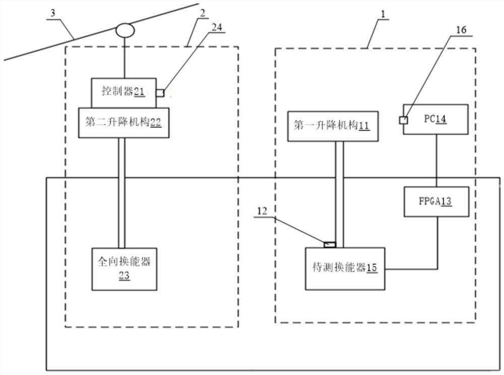
[0041] Below according to the attached drawings Figure 3 to Figure 6 , the preferred embodiments of the present invention are given and described in detail, so that the functions and characteristics of the present invention can be better understood.

[0042] see Figure 3 to Figure 6 , a broadband multi-beam sonar array directivity test system according to an embodiment of the present invention includes a first trolley 1, a second trolley 2 and a slide rail 3; the first trolley 1 includes a first lifting mechanism 11, a The laser range finder 12 , an FPGA 13 and a PC 14 , the first lifting mechanism 11 drives and connects a transducer to be measured 15 and the laser range finder 12 , the laser range finder 12 is connected to the PC 14 , and the transducer 15 to be measured is connected through the FPGA 13 PC14; The second trolley 2 includes a controller 21, a second lift mechanism 22 and an omnidirectional transducer 23, the controller 21 is connected to the second lift mech...


PUM


Abstract

The invention provides a broadband multi-beam sonar array directivity test system and method. The system comprises a first trolley, a second trolley and a sliding rail. The first trolley comprises a first lifting mechanism, a laser range finder, an FPGA (Field Programmable Gate Array) and a PC (Personal Computer), the first lifting mechanism is in transmission connection with a transducer to be measured and the laser range finder, the laser range finder is connected with the PC, and the transducer to be measured is connected with the PC through the FPGA; the second trolley comprises a controller, a second lifting mechanism and an omnidirectional transducer, the controller is connected with the second lifting mechanism and the sliding rail, and the second lifting mechanism is in transmission connection with the omnidirectional transducer; and the sliding rail is in transmission connection with the second trolley. According to the broadband multi-beam sonar array directivity test system and method, more test time can be saved, more beams can be measured, gain compensation can be carried out according to the current position, and therefore errors caused in the test process are reduced, and the test accuracy is improved.

Description

technical field [0001] The invention relates to the technical field of beamforming result testing, in particular to a broadband multi-beam sonar array directivity testing system and method. Background technique [0002] As an important fishing instrument in marine fishery, multi-beam fishing sonar uses the signal reflected back after the sound wave encounters the target to detect the position and size of the target. Beamforming is the core technology in the development of multi-beam fishing sonar, and multi-beam directivity testing is an important part of beamforming verification. [0003] The existing methods for directivity testing of sonar arrays mainly include: 1. Manual measurement, that is, the waveform received by the hydrophone or omnidirectional transducer is manually read from the oscilloscope every time the transducer rotates a certain number of degrees. Peak-to-peak value, when the echo waveform is irregular, it is necessary to perform multi-point reading to obt...

Claims


Application Information

Patent Timeline
Patent Type & Authority Applications(China)
IPC IPC(8): G01S7/52
CPCG01S7/52004
Inventor 程婧王志俊魏珂李国栋
Owner FISHERY MACHINERY & INSTR RES INST CHINESE ACADEMY OF FISHERY SCI
Why Eureka
Eureka Blog
Learn More