Optimization method of isolation column super junction structure

An optimization method, a technique for isolating columns, used in design optimization/simulation, constraint-based CAD, calculations, etc.

Active Publication Date: 2022-07-22
UNIV OF ELECTRONICS SCI & TECH OF CHINA +1
View PDF4 Cites 0 Cited by
  • Summary
  • Abstract
  • Description
  • Claims
  • Application Information

AI Technical Summary

Problems solved by technology

However, in the prior art, there is no comparison of the on-resistance (Specific ON-Resistor, R on,sp ) to optimize and determine the technology of the super junction structure of silicon dioxide spacers and intrinsic silicon spacers

Method used


Image

  • Optimization method of isolation column super junction structure
  • Optimization method of isolation column super junction structure
  • Optimization method of isolation column super junction structure

Examples


Embodiment

[0047] A method for optimizing an isolation column superjunction structure, comprising the following steps:

[0048] Step 1. Build the objective function:

[0049]

[0050] where R on,sp (T) represents the specific on-resistance at temperature T, W represents the thickness of the n-column and p-column in the superjunction structure, q represents the unit charge, μ n (T) represents the electron mobility at temperature T (the subscript n represents electrons), N represents the doping concentration of n-column and p-column (the doping concentration of n-column and p-column is the same); n(T) represents the electron concentration at temperature T, A(T) is a parameter related to temperature T, which can be obtained by solving the following equation:

[0051]

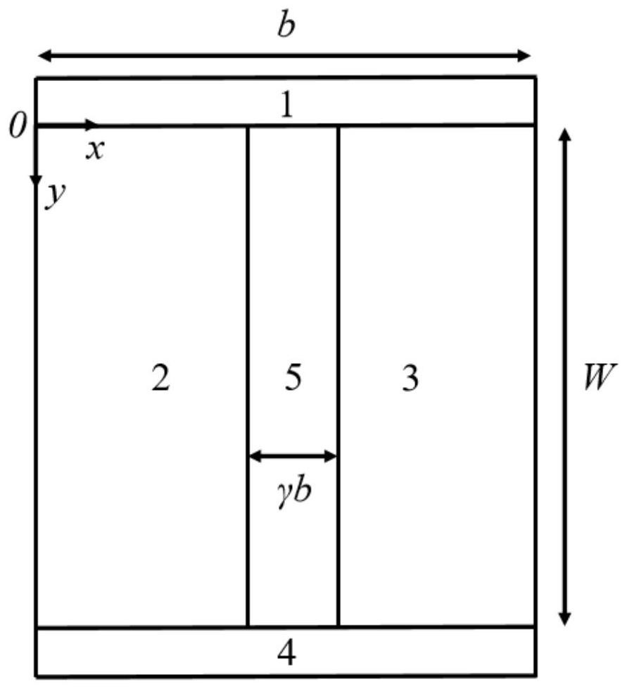
[0052] where c(T) is an exponential function related to temperature, c(T)=exp{-1.08+4.73×10 -4 ×[9×10 4 / 936-T 2 / (T+636)] / 0.0258}, γ represents the ratio between the width of the isolation pillar 5 and the widt...


PUM


Abstract

The optimization method of the isolation column super-junction structure is suitable for the super-junction structure of any application condition, the influence of temperature is comprehensively considered, all optimized design parameters are obtained through one objective function and two constraint conditions, and the optimization method is suitable for the super-junction structure of any application condition. Results with different error precisions can be obtained by performing iteration of different times through the same optimization process. Compared with a traditional super-junction structure, the isolation column super-junction structure obtained through the optimization method has a lower specific on-resistance design parameter value range, and the superiority of the low-dielectric-coefficient dielectric isolation column super-junction structure is proved.

Description

technical field [0001] The invention belongs to the technical field of semiconductor devices, and in particular relates to an optimization method for a low-dielectric coefficient isolation column superjunction structure. Background technique [0002] In power electronics technology, the proposal of superjunction structure breaks the silicon limit problem existing in power devices. Traditional superjunction structures such as figure 1 shown. Due to the absorption of the electric field lines in the n-column by the p-column, a part of the electric field lines that originally entered the channel through the n-column vertically becomes horizontal and enters the p-column and then returns to the channel, which greatly optimizes the electric field distribution inside the structure and reduces the the peak electric field strength. Compared with the traditional withstand voltage layer, the doping concentration of the superjunction structure can be greatly improved under the same bre...

Claims


Application Information

Patent Timeline
Patent Type & Authority Applications(China)
IPC IPC(8): G06F30/39G06F30/20G06F111/04G06F119/08
CPCG06F30/39G06F30/20G06F2119/08G06F2111/04Y02E40/60
Inventor 张浩悦黄海猛郭新凯童星豪
Owner UNIV OF ELECTRONICS SCI & TECH OF CHINA
Why Eureka
Try Eureka