Eureka AIR delivers breakthrough ideas for toughest innovation challenges, trusted by R&D personnel around the world.

C-band full-cavity extraction relativistic magnetron

A relativistic magnetron and C-band technology, which is applied in the field of C-band full-cavity extraction relativistic magnetron, can solve the problems of reduced RM efficiency and power capacity, increased extraction difficulty, and reduced mode interval, so as to improve power The effect of capacity, high efficiency and high power microwave output

Pending Publication Date: 2022-07-22
NAT UNIV OF DEFENSE TECH
View PDF0 Cites 0 Cited by
  • Summary
  • Abstract
  • Description
  • Claims
  • Application Information

AI Technical Summary

Problems solved by technology

However, at present, RM mainly works in the L or S band. When the working frequency band is further extended to the C band, its structure becomes complicated, the mode interval becomes smaller, the difficulty of extraction is further increased, and the efficiency and power capacity of RM become smaller.

Method used


Image

  • C-band full-cavity extraction relativistic magnetron
  • C-band full-cavity extraction relativistic magnetron
  • C-band full-cavity extraction relativistic magnetron

Examples


Embodiment Construction

[0032] The accompanying drawings constituting a part of the present application are used to provide further understanding of the present invention, and the exemplary embodiments of the present invention and their descriptions are used to explain the present invention and do not constitute an improper limitation of the present invention.

[0033] In order to illustrate the technical solutions of the present invention, the following specific embodiments are used for description.

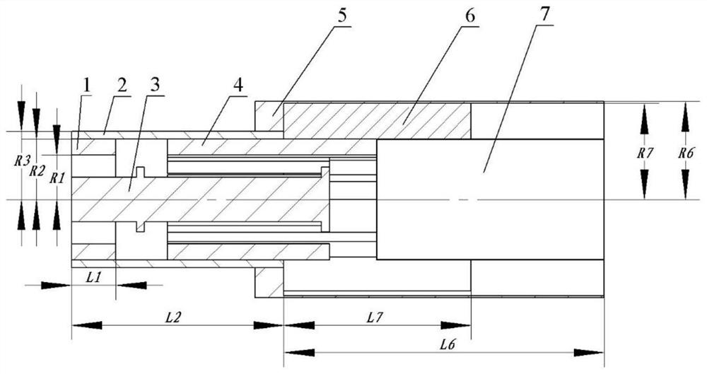
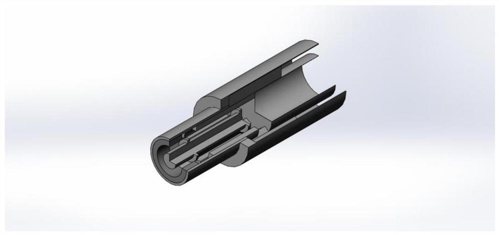
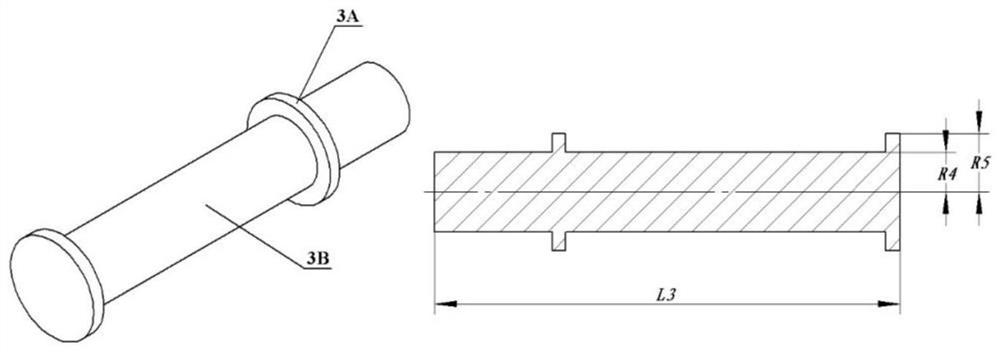
[0034] like figure 1 , figure 2 As shown, a C-band full cavity extraction relativistic magnetron includes an input inner conductor 1, an input outer conductor 2, a cathode 3, an anode 4, an output outer conductor 5, a first output inner conductor 6 and a second output inner conductor 7 ;

[0035] The input inner conductor 1, the input outer conductor 2, the cathode 3, the anode 4, the output outer conductor 5, the first output inner conductor 6 and the second output inner conductor 7 are all rotatio...


PUM

PropertyMeasurementUnit
Axial lengthaaaaaaaaaa
Wall thicknessaaaaaaaaaa
Thicknessaaaaaaaaaa

Abstract

The invention belongs to the technical field of high-power microwaves. The invention provides a C-band full-cavity extraction relativistic magnetron. The C-band full-cavity extraction relativistic magnetron comprises an input inner conductor (1), an input outer conductor (2), a cathode (3), an anode (4), an output outer conductor (5), a first output inner conductor (6) and a second output inner conductor (7). The C-band full-cavity extraction relativistic magnetron provided by the invention has the advantages of compact structure, suitability for permanent magnet packaging, easiness in mode conversion and the like, and meanwhile, high-power and high-efficiency output of C-band microwaves can be realized.

Description

technical field [0001] The invention belongs to the technical field of high-power microwaves, and in particular relates to a C-band full cavity extraction relativistic magnetron. Background technique [0002] High-power microwaves usually refer to electromagnetic waves with peak power greater than 100MW and frequencies between 1GHz and 300GHz. At present, high-power microwaves are widely used in the power supply of satellites and space platforms, the launch of small deep-space probes, the propulsion system of orbiter altitude change, electronic high-energy radio frequency accelerators, and material processing and processing. [0003] The high-power microwave source is the core component for generating high-power microwaves, which utilizes the interaction of high-current electron beams and resonators to generate high-power microwaves. Among many high-power microwave sources, the Relativistic MagnetRon (RM) has always been a research hotspot due to its high efficiency, compac...

Claims


Application Information

Patent Timeline
IPC IPC(8): H01J25/52H01J23/15
CPCH01J25/52H01J23/15
Inventor 樊玉伟徐浩东刘则阳
Owner NAT UNIV OF DEFENSE TECH
Why Eureka
Eureka Blog
Learn More