Electrostatic discharge clamping circuit and multi-point synchronous static discharge method

An electrostatic discharge and clamping circuit technology, which is applied to circuit devices, emergency protection circuit devices for limiting overcurrent/overvoltage, emergency protection circuit devices, etc. Burning, affecting chip ESD performance and other issues, to achieve the effect of improving electrostatic discharge capability and reliability

Pending Publication Date: 2022-07-22
HYGON INFORMATION TECH CO LTD
View PDF0 Cites 1 Cited by
  • Summary
  • Abstract
  • Description
  • Claims
  • Application Information

AI Technical Summary

Problems solved by technology

MCP chips containing multi-chip packaging systems are very prone to ESD events. In order to ensure the ESD protection capability of ultra-large-scale chips, one or more clamping circuits are widely used in the chip. It is difficult to place a clamping circuit in the chip. The discharge of static electricity at different positions is required, but when multiple clamping circuits are placed at different positions on the chip, due to the distance between the clamping circuits and the difference in the parasitic network of the clamping circuits at different positions, the clamping circuits cannot be effective Working together, it often happens that part of the clamping circuit is turned on first for electrostatic discharge, and part of the clamping circuit is not turned on in time, resulting in the burning of the clamping circuit and affecting the ESD performance of the chip

Method used


Image

  • Electrostatic discharge clamping circuit and multi-point synchronous static discharge method
  • Electrostatic discharge clamping circuit and multi-point synchronous static discharge method
  • Electrostatic discharge clamping circuit and multi-point synchronous static discharge method

Examples


Embodiment Construction

[0029] In order to make the objects, technical solutions and advantages of the present disclosure more apparent, exemplary embodiments according to the present disclosure will be described in detail below with reference to the accompanying drawings. Obviously, the described embodiments are only some of the embodiments of the present disclosure, not all of the embodiments of the present disclosure, and it should be understood that the present disclosure is not limited by the example embodiments described herein.

[0030] Furthermore, in this specification and the drawings, steps and elements having substantially the same or similar elements are denoted by the same or similar reference numerals, and repeated descriptions of these steps and elements will be omitted.

[0031] As shown in this application and in the claims, unless the context clearly dictates otherwise, the words "a", "an", "an" and / or "the" are not intended to be specific in the singular and may include the plural....


PUM


Abstract

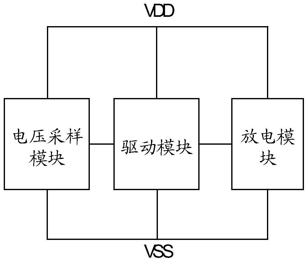
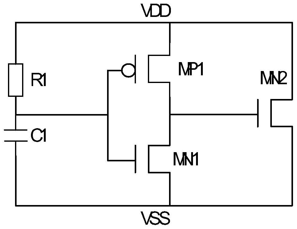
The embodiment of the invention provides an electrostatic discharge clamping circuit and a multi-point synchronous electrostatic discharge method. The circuit provided by the embodiment of the invention is connected between a power supply and the ground, the power supply is provided with at least two connecting ends, and the circuit comprises a voltage sampling module which is configured to receive a power supply voltage at a first connecting end of the at least two connecting ends and is used for providing a first control voltage for a first node; the driving module drives the discharging module to work; the first discharging module is used for releasing electrostatic charges of the first connecting end to the ground; and the second discharging module is used for releasing electrostatic charges of at least one part of the at least two connecting ends except the first connecting end to the ground, so that the requirement of synchronously releasing static electricity at different positions through one electrostatic discharge clamping circuit in a super-large-scale chip is met, and the reliability of the super-large-scale chip is improved. And the reliability of the electrostatic discharge clamping circuit and the ESD protection capability of the chip are improved.

Description

technical field [0001] The present disclosure relates to the technical field of integrated circuit design, and more particularly, to an electrostatic discharge clamp circuit, a chip, a multi-chip package, a multi-chip system, and a method for synchronously discharging static electricity at multiple points. Background technique [0002] With the improvement of the chip manufacturing process level, the scale of the chip is getting larger and larger, and the requirements for the chip size are getting higher and higher. Getting lower and lower, all of which put forward higher requirements for the ESD protection capability of Electro-Static Discharge (ESD) circuits. [0003] At the same time, with the development of modern integrated circuit technology, in order to meet various application requirements, more and more large-scale and ultra-large-scale integrated circuit die (Die) are packaged on a package substrate, forming a multi-chip package (Multi-chip package). -Chip-Package...

Claims


Application Information

Patent Timeline
Patent Type & Authority Applications(China)
IPC IPC(8): H02H9/04H02H7/20
CPCH02H9/04H02H7/20
Inventor 刘勇江金军贵张阳
Owner HYGON INFORMATION TECH CO LTD
Why Eureka
Try Eureka