Storage tank cleaning device and method

A technology for cleaning devices and storage tanks, applied in cleaning methods and utensils, chemical instruments and methods, cleaning hollow objects, etc., can solve the problems of acid-base solution, large water consumption, high safety hazards, and high cleaning costs, and achieves a reduction in The effect of water waste, lower use cost, and high cleaning safety

Active Publication Date: 2022-07-26
CHINA NAT CHEM ENG THIRD CONSTR
View PDF6 Cites 1 Cited by
  • Summary
  • Abstract
  • Description
  • Claims
  • Application Information

AI Technical Summary

Problems solved by technology

[0003] However, the above storage tank cleaning device has the following defects in use: high cleaning cost, poor work efficiency, unsatisfactory effect, and great safety hazards. The existing cleaning device can only be cleaned by a single device, and the amount of acid and alkali liquid and water used for cleaning is large. , and cannot be reused, and the discharged cleaning waste liquid has environmental protection problems

Method used


Image

  • Storage tank cleaning device and method
  • Storage tank cleaning device and method
  • Storage tank cleaning device and method

Examples


Embodiment 1

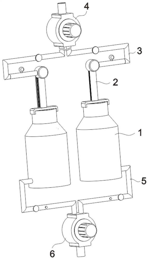
[0036] see figure 1 , a storage tank cleaning device, applied to multiple groups of storage tank main bodies 1 to perform synchronous cleaning operations, the cleaning device includes a rotary chemical cleaning component disposed on the top of the storage tank main body 1 for cleaning the interior of the storage tank main body 1 2;

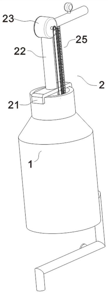
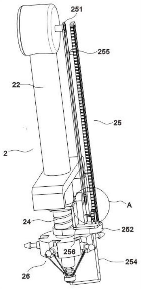
[0037] further, as figure 2 As shown, the rotary chemical cleaning assembly 2 includes a support frame 21 clamped on the top of the tank main body 1, a water inlet pipe 22 is fixed on the top of the support frame 21, and a threaded pipe 24 is inserted at the bottom of the water inlet pipe 22. The threaded pipe 24 The outer thread of the outer wall is connected with the inner thread of the inner wall of the water inlet pipe 22, so that the threaded pipe 24 can be rotated upwards or downwards. The top of the 22 is provided with a guide shell 23 that communicates with each other, and a follower impeller ((from the attached Figure 5 It can be see...

Embodiment 2

[0044] like Figure 6-7 As shown, the variable-direction nozzle 26 includes a hollow seat 261 disposed at the bottom of the threaded pipe 24 and communicated with it, and a plurality of groups of notches are provided in an annular array on the outer wall of the hollow seat 261, and the notches are rotated by a rotating shaft and a torsion spring. A nozzle main body 262 is provided. The outer wall of the nozzle main body 262 is provided with a branch pipe 263 that communicates with the inner cavity of the hollow seat 261 .

[0045] Among them, the function of the rotating shaft and the torsion spring enables one end of the nozzle body 262 to be turned downward, so that the cleaning range is wider when cleaning the bottom of the inner cavity of the tank body 1, and at the same time, the nozzle body 262 can be reset under the action of the torsion spring. to the horizontal state.

Embodiment 3

[0047] like Figure 6-7 As shown, a sealing cylinder 265 is provided at the center of the bottom of the hollow seat 261, a piston (not shown in the figure) is arranged in the inner cavity of the sealing cylinder 265, and the piston is fixedly sleeved on the top of the outer wall of the piston rod, and the top and bottom of the piston rod are both Hollow, wherein the bottom of the piston rod is communicated with one end of the connecting air pipe 254 through a rotary joint 267, a return spring is sleeved on the outer wall of the piston rod, a connecting ring 264 is sleeved at the bottom of the outer wall of the piston rod, and the outer wall of the connecting ring 264 is annularly arrayed A plurality of groups of connecting ropes 266 are provided, and the plurality of groups of connecting ropes 266 are in one-to-one correspondence with the nozzle main body 262, and the other end of the connecting rope 266 is connected with the bottom outer end of the nozzle main body 262;

[00...


PUM


Abstract

The invention relates to a storage tank cleaning device in the technical field of storage tank cleaning devices, which is applied to multiple groups of storage tank main bodies, synchronously cleans the interiors of the multiple groups of storage tank main bodies, and comprises a rotary chemical cleaning assembly which is arranged at the top of the storage tank main bodies and is used for cleaning the interiors of the storage tank main bodies. The rotary chemical cleaning assembly is arranged at the top of the storage tank body, a follow-up impeller is driven by flowing of cleaning liquid, then a tooth-missing gear, a follow-up gear and a driving gear drive a rack to enable a guide frame to move downwards, the guide frame drives a linkage plate to enable a threaded pipe to move downwards, and cleaning is achieved. And therefore, the direction-variable nozzle rotates up and down in a reciprocating manner for spraying and cleaning, and the cleaning range, the cleaning efficiency and the cleaning quality of the interior of the storage tank body are improved.

Description

technical field [0001] The invention relates to the technical field of storage tank cleaning devices, in particular to a storage tank cleaning device and method. Background technique [0002] At present, more and more storage tanks are put into use in petrochemical plants, and the requirements for chemical cleaning of storage tanks, especially those made on site, will become increasingly strict. The existing chemical cleaning method usually transports the acid and alkali liquid to be cleaned into the storage tank through a pressurized pump, manually enters the interior after setting up a scaffold for cleaning, and discharges through the sewage outlet at the bottom of the storage tank after cleaning. [0003] However, the above-mentioned storage tank cleaning device has the following defects in use: high cleaning cost, poor work efficiency, unsatisfactory effect, and large safety hazard. The existing cleaning device can only be cleaned by a single device, and the amount of ac...

Claims


Application Information

Patent Timeline
Patent Type & Authority Applications(China)
IPC IPC(8): B08B9/093
CPCB08B9/0936
Inventor 叶雷生
Owner CHINA NAT CHEM ENG THIRD CONSTR
Why Eureka
Try Eureka