Eureka AIR delivers breakthrough ideas for toughest innovation challenges, trusted by R&D personnel around the world.

Solar street lamp with protection structure and protection method

A technology of solar street lamps and protective structures, applied in the field of solar street lamps, can solve the problems of increasing the weight of lamp poles, elastic polyurethane blocks, poor anti-collision effect of air bags, damage to street lamps, etc., and achieves good protection effects.

Inactive Publication Date: 2022-07-26
JIANGSU HUAHAO NEW ENERGY CO LTD
View PDF2 Cites 0 Cited by
  • Summary
  • Abstract
  • Description
  • Claims
  • Application Information

AI Technical Summary

Problems solved by technology

[0003] The traditional street lamps are installed directly on the base of the ground, and because there are many vehicles on urban roads, the lampposts are easily hit by out-of-control vehicles, resulting in damage to the street lamps.
[0004] The Chinese patent with the application number CN202021170650.8 applied for a street light pole with a protective structure, which uses anti-collision components and fixed components, and is equipped with anti-collision rings and anti-collision columns. Although it can achieve the effect of anti-collision, But it also increases the weight of the light pole, which is inconvenient when installing the light pole for construction
[0005] And the Chinese patent with the application number CN202120318429.0 applied for a solar street lamp with a protective structure. An inner cylinder, an outer cylinder, an elastic polyurethane block and an airbag are set up, and redundant structures are added. When hitting, the impact force is generally Relatively large, the elastic polyurethane block and the airbag anti-collision effect are not good

Method used


Image

  • Solar street lamp with protection structure and protection method
  • Solar street lamp with protection structure and protection method
  • Solar street lamp with protection structure and protection method

Examples


Embodiment Construction

[0045] The technical solutions in the embodiments of the present invention will be clearly and completely described below with reference to the accompanying drawings in the embodiments of the present invention. Obviously, the described embodiments are only a part of the embodiments of the present invention, rather than all the embodiments. Based on the embodiments of the present invention, all other embodiments obtained by those of ordinary skill in the art without creative efforts shall fall within the protection scope of the present invention.

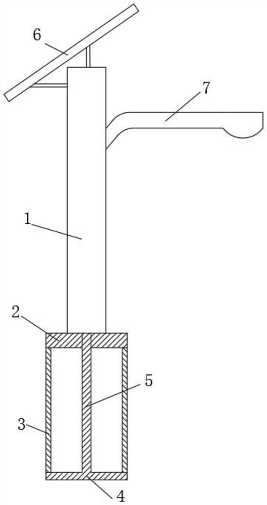
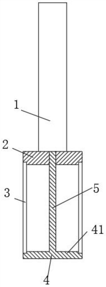
[0046] see Figure 1-3 , This embodiment provides a solar street light with a protective structure, including a light pole 1, and the light pole 1 is used to install and support the working parts of the street light. A support ring 2 is installed at the bottom of the light pole 1, and a support rod 5 is also installed at the bottom of the light pole 1. The inside of the support rod 5 is provided with a threading hole, which can be us...


PUM


Abstract

The invention discloses a solar street lamp with a protection structure and a protection method, and relates to the field of solar street lamps, the solar street lamp comprises a lamp pole, a supporting ring is mounted at the bottom of the lamp pole, a supporting rod is further mounted at the bottom of the lamp pole, a mounting plate is arranged at the bottom of the supporting rod, and a protection ring is mounted between the supporting ring and the mounting plate; a space is reserved between the inner side of the protection ring and the supporting rod, a solar power generation panel is fixedly installed on the top of the lamp pole through the supporting rod, a lamp holder is fixedly installed on one side of the upper end of the lamp pole, and a bulb is installed on the lamp holder. By arranging the supporting ring, the mounting plate and the protection ring arranged between the supporting ring and the mounting plate, the protection ring deforms when being impacted, part of impact force can be counteracted, the supporting ring and the mounting plate can generate opposite acting force on deformation of the protection ring in the deformation process of the protection ring, and the acting force counteracts the impact force borne by the protection ring 3; therefore, larger impact force can be borne.

Description

technical field [0001] The invention relates to the field of solar street lamps, in particular to a solar street lamp with a protective structure and a protection method. Background technique [0002] Solar street lights are street lights powered by crystalline silicon solar cells and used to replace traditional public power lighting. No need to lay cables, no AC power supply, no electricity bill; DC power supply, photosensitive control; good stability, long life, high luminous efficiency, easy installation and maintenance, high safety performance, energy saving, environmental protection, economical and practical advantages. It can be widely used in urban main and secondary roads, communities, factories, tourist attractions, parking lots and other places. [0003] In traditional street lights, the light poles are directly installed on the base of the ground. Since there are many vehicles on urban roads, the street light poles are easily hit by out-of-control vehicles, resul...

Claims


Application Information

Patent Timeline
Patent Type & Authority Applications(China)
IPC IPC(8): F21S9/03F21V15/01F21V15/04F21W131/103
CPCF21S9/035F21V15/012F21V15/04F21W2131/103
Inventor 周晓娟周娥周建
Owner JIANGSU HUAHAO NEW ENERGY CO LTD
Why Eureka
Eureka Blog
Learn More