Handheld electric vacuum cleaner

A vacuum cleaner, hand-held technology, applied in the directions of vacuum cleaners, handles, cleaning methods, etc., can solve problems such as noise fan damage, and achieve the effect of suppressing damage, reducing noise, and efficiently collecting

Pending Publication Date: 2022-07-29
YAMABIKO CORP
View PDF1 Cites 0 Cited by
  • Summary
  • Abstract
  • Description
  • Claims
  • Application Information

AI Technical Summary

Problems solved by technology

Therefore, the conventional vacuum cleaner has the problem that the fan of the blower comes into contact with the sucked matter, thereby generating noise or causing damage to the fan.

Method used


Image

  • Handheld electric vacuum cleaner
  • Handheld electric vacuum cleaner
  • Handheld electric vacuum cleaner

Examples


Embodiment Construction

[0022] Embodiments of the present invention will be described below with reference to the accompanying drawings. In the following description, the same symbols in different drawings represent parts with the same functions, and therefore, repeated descriptions in the respective drawings will be omitted as appropriate.

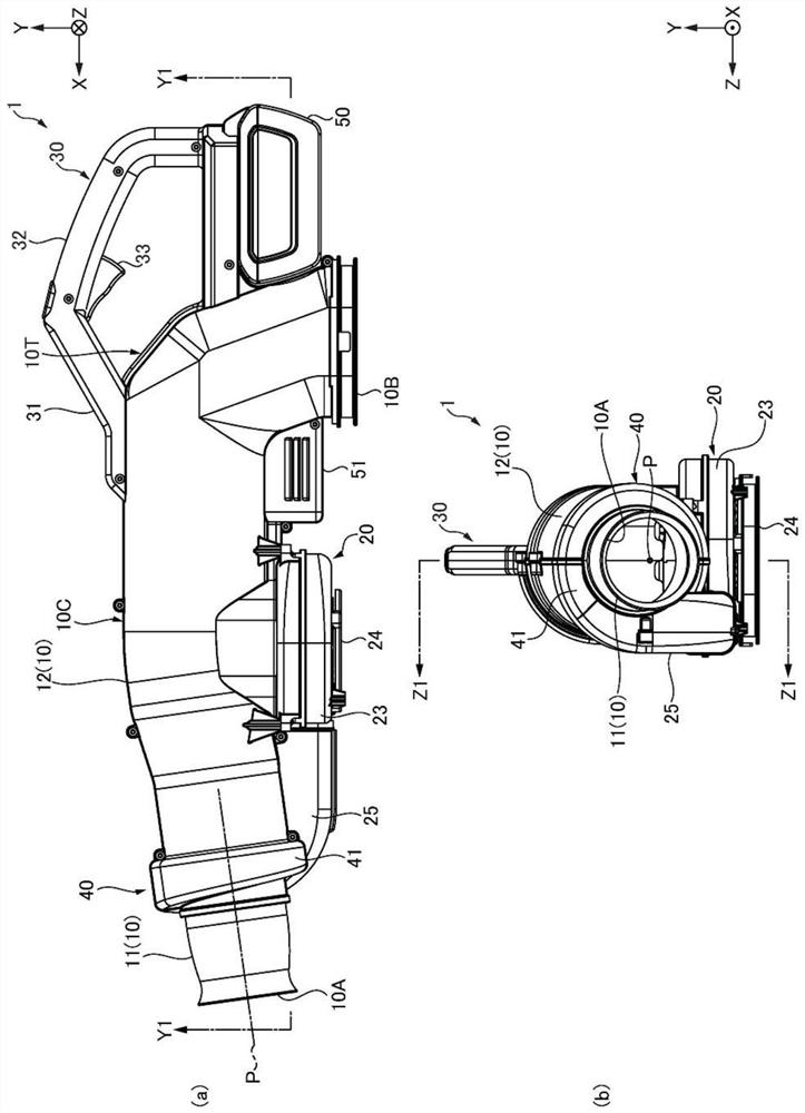
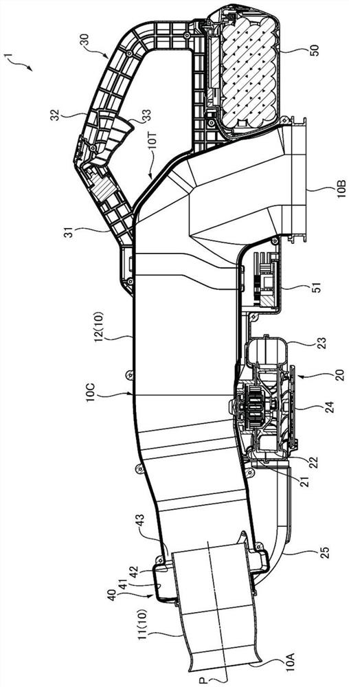
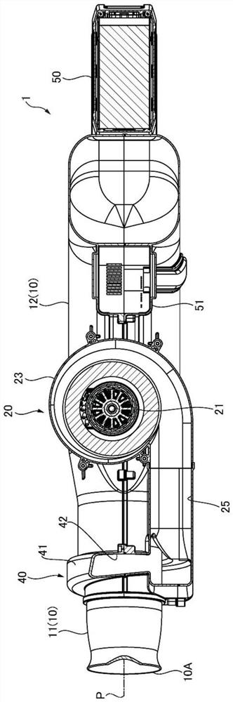
[0023] like Figure 1 to Figure 3 As shown, a hand-held electric vacuum cleaner (hereinafter referred to as a vacuum cleaner) 1 is a hand-held working machine for suction operation, which includes a pipe tube 10 for suctioning dust or crop residues, a blower 20, a handle 30 , and the injector unit 40 .

[0024] The tube 10 has a suction port 10A at one end and a discharge port 10B at the other end, and discharges the aspirated material sucked into the tube 10 through the suction port 10A from the discharge port 10B. During the suction operation, a collection bag or the like, not shown, is attached to the discharge port 10B.

[0025] In the illustrated example...


PUM


Abstract

The invention aims to solve the technical problems that for a vacuum dust collector which performs suction operation, noise during operation is reduced, damage to an air blower of the vacuum dust collector is inhibited, large sucked objects are efficiently collected, and suction (the vacuum dust collector) and air blowing (the air blower) are easily switched. According to the technical scheme, the handheld electric vacuum cleaner is provided with a pipe barrel, one end of the pipe barrel is provided with a suction inlet, and the other end of the pipe barrel is provided with a discharge outlet; a blower which is provided on the outside of the tube and which is driven by an electric motor; the handheld handle is arranged on the outer side of the pipe barrel and is close to the discharge port in the length direction of the pipe barrel; and the ejector unit is arranged close to the suction inlet in the length direction of the pipe barrel, and is used for feeding the air flow with pressure generated by the air feeder into the pipe barrel from the periphery of the pipe barrel and ejecting the air flow towards the exhaust port.

Description

technical field [0001] The invention relates to a hand-held electric vacuum cleaner for suctioning dust, crop residues and the like. Background technique [0002] A vacuum cleaner for suctioning and collecting dust such as fallen leaves or crop residues (hereinafter referred to as suction operation), which generates suction pressure ( Negative pressure), sucking dust, etc. into the tube from the suction port at one end of the tube, and collecting the sucked dust and other suction materials from the discharge port at the other end of the tube into a collector such as a bag (refer to the following Patent Document 1). [0003] prior art literature [0004] Patent Literature [0005] [Patent Document 1] Specification of US Patent No. 9874225 SUMMARY OF THE INVENTION [0006] The technical problem to be solved by the invention [0007] In order to make the inside of the tube into a negative pressure, the above-mentioned traditional vacuum cleaner will use a blower to suck ...

Claims


Application Information

Patent Timeline
Patent Type & Authority Applications(China)
IPC IPC(8): A47L5/24A47L7/00A47L9/32A47L9/28F04D25/08F04D29/42
CPCA47L5/24A47L7/00A47L9/322A47L9/2884F04D25/08F04D29/4226A01G20/47E01H1/0863E01H1/0809E01H1/12A47L9/248
Inventor 铃木贤司
Owner YAMABIKO CORP
Why Eureka
Try Eureka