Building cement block pressure detection device
A technology of construction cement and detection device, which is applied in the direction of measuring device, using stable tension/pressure test material strength, instrument, etc. Effect
- Summary
- Abstract
- Description
- Claims
- Application Information
AI Technical Summary
Problems solved by technology
Method used
Image
Examples
Embodiment 1
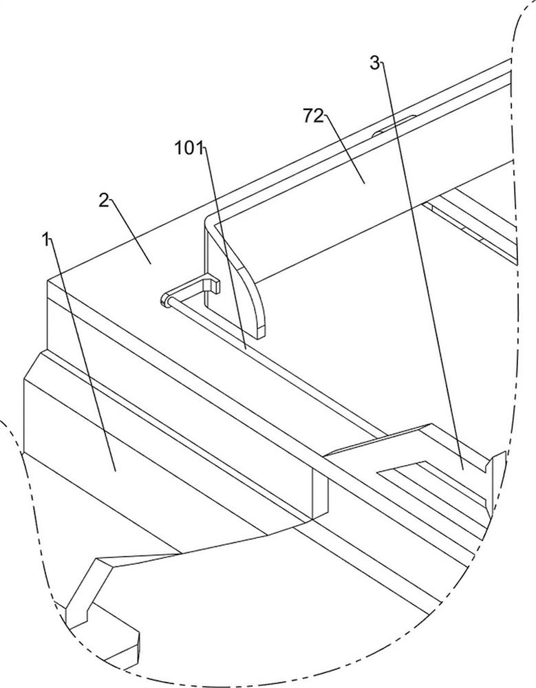
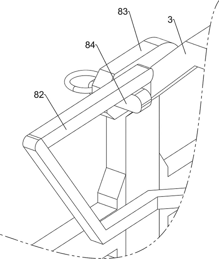
[0036] A construction cement block pressure detection device, such as Figure 1-7As shown, it includes a fixed frame 1, a fixed plate 2, a first connecting rod 3, a second connecting rod 4, a pressure plate 5, a first spring 6, a push-open mechanism 7 and a spread-open mechanism 8, and the top of the fixed frame 1 is bolted A fixed plate 2 is connected, the middle part of the front side of the fixed plate 2 is opened with a word notch, a first connecting rod 3 is welded between the left and right of the top rear side of the top of the fixed plate 2, and the middle part of the first connecting rod 3 is slidably provided with a second connecting rod 3. The connecting rod 4, the lower end face of the second connecting rod 4 is provided with a pressing plate 5, the pressing plate 5 is used to squeeze the building cement block, the outer side of the lower part of the second connecting rod 4 is covered with a first spring 6, and the first spring 6 is The two ends are respectively co...
Embodiment 2
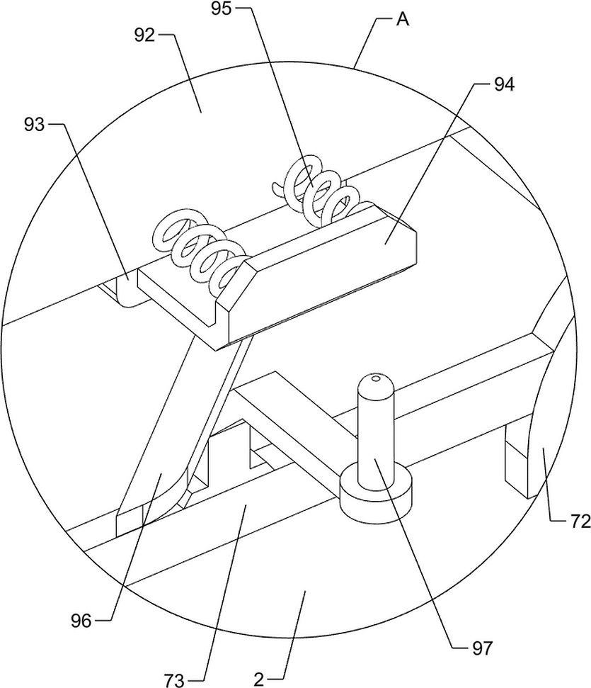
[0041] On the basis of Example 1, as figure 1 , Figure 8 and Figure 9 As shown, it also includes a blanking mechanism 9, and the blanking mechanism 9 includes a second fixed block 91, a blanking frame 92, a third fixed block 93, a clamping plate 94, a second spring 95, an inclined plate 96 and a seventh connection Rod 97, a second fixing block 91 is connected by bolts between the left and right sides of the front side of the top of the fixing plate 2, and a blanking frame 92 is fixed between the middle position of the upper part of the second fixing block 91 and the first connecting rod 3, The blanking frame 92 is used to hold the building cement blocks. The bottom of the blanking frame 92 is symmetrically welded with a third fixing block 93. The two third fixing blocks 93 are slidably provided with a clamping plate 94. The clamping plate 94 is connected to the adjacent one. Two second springs 95 are connected between the blanking frames 92 on the side, the outer sides of ...
Embodiment 3
[0044] On the basis of Example 2, as figure 1 , Figure 10 , Figure 11 and Figure 12 As shown, it also includes a lifting mechanism 10. The lifting mechanism 10 includes a pulling rope 101, a second baffle 102, a first pulley 103, a second pulley 104, a fixing rod 105, a third spring 106, a placing plate 107 and a limiter Plate 108, the rear side of the top of the fixing frame 1 is fixed to the limit plate 108 by bolts, the left and right sides of the limit plate 108 are welded with fixing rods 105, and the upper part of the two fixing rods 105 is slidably provided with a placing plate 107 , the inner bottom of the placing plate 107 is hollow, the outer sides of the lower parts of the two fixing rods 105 are sleeved with a third spring 106, and the two ends of the third spring 106 are respectively connected to the placing plate 107 and the limit plate 108. The rear side of the connecting rod 3 is symmetrically welded with a second baffle 102 , the inner sides of the lower...
PUM
 Abstract
Description
Claims
Application Information
 - R&D
- Intellectual Property
- Life Sciences
- Materials
- Tech Scout
- Unparalleled Data Quality
- Higher Quality Content
- 60% Fewer Hallucinations
Browse by: Latest US Patents, China's latest patents, Technical Efficacy Thesaurus, Application Domain, Technology Topic, Popular Technical Reports.
© 2025 PatSnap. All rights reserved.Legal|Privacy policy|Modern Slavery Act Transparency Statement|Sitemap|About US| Contact US: help@patsnap.com


