Laser-assisted cutting tool

A cutting tool and laser-assisted technology, applied in the field of precision parts processing, can solve the problems of poor improvement effect and lack of effective irradiation of materials, and achieve the effect of improving effect, improving surface quality and improving performance

Pending Publication Date: 2022-07-29
INST OF OPTICS & ELECTRONICS - CHINESE ACAD OF SCI +1
View PDF6 Cites 0 Cited by
  • Summary
  • Abstract
  • Description
  • Claims
  • Application Information

AI Technical Summary

Problems solved by technology

[0003] In the field of single-point diamond cutting, there are two main methods for the application of laser-assisted processing in the existing technology. The first method is that the laser is directly irradiated from the outside of the tool to the contact area between the tool tip and the processed material or its vicinity, forming a local high temperature to improve Cutting performance, but because external factors such as cutting fluid affect the laser transmission path during the cutting process, the improvement effect is not good; the second method is that the laser passes through the interior of the diamond blade and then enters the tool tip, forming a small The incident angle of the laser can be emitted from the flank and seep into the surface of the material in a very small area of ​​the tool tip. Because the incident angle of the laser on the rake is relatively large at this time, limited by the phenomenon of total reflection of light, the laser often cannot The rake face is shot out, the material near the rake face to be cut cannot be effectively irradiated, and the cutting effect is not improved well

Method used


Image

  • Laser-assisted cutting tool
  • Laser-assisted cutting tool
  • Laser-assisted cutting tool

Examples


Embodiment Construction

[0025] The present invention will be further described below with reference to the accompanying drawings and specific embodiments.

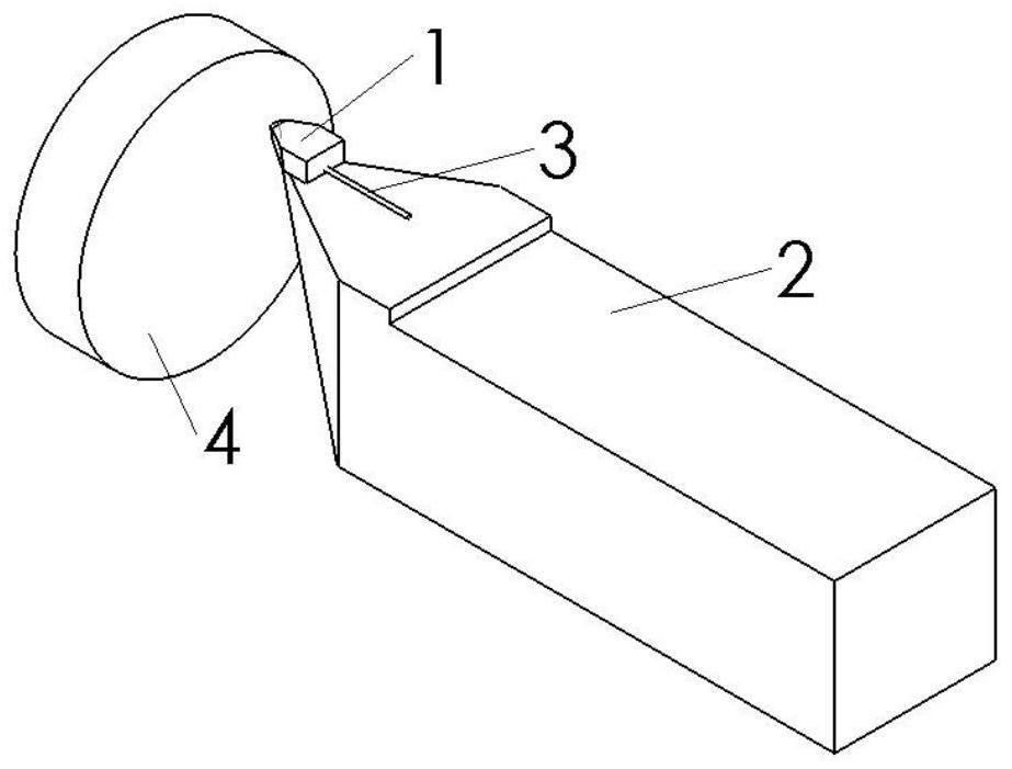
[0026] figure 1 It is a three-dimensional diagram of the structure and application scene of a laser-assisted cutting tool of the present invention, including: a tool particle 1 and a tool handle 2 . The tool holder 2 is a conventional structure, generally designed and dimensioned according to the tool holder of the machine tool, and will not be repeated here.

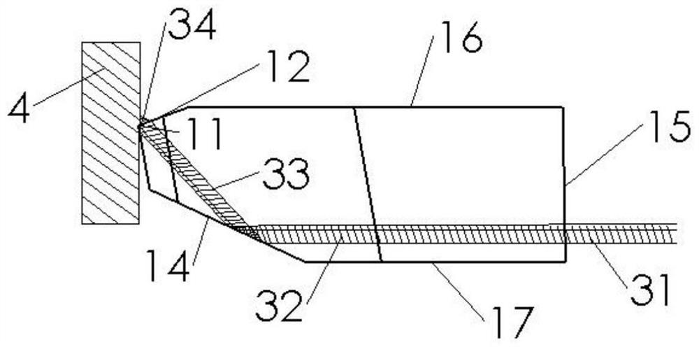
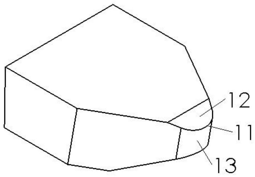
[0027] figure 2 This is a diagram of the blade structure and optical path transmission of a laser-assisted cutting tool of the present invention. The blade 1 is made of a hard laser-transmitting material, usually single crystal diamond, but is not limited to this material. The blade 1 has a special structure, including: a blade tip 11 , a rake face 12 , a flank 13 , an internal reflection surface 14 , a laser incident surface 15 , a blade top surface 16 , and a blade bottom surface 17 ....


PUM


Abstract

The invention discloses a laser-assisted cutting tool which comprises a tool blade (1) and a tool handle (2), and the tool blade (1) is welded to one end of the tool handle (2). According to the laser-assisted cutting tool, a laser beam (3) is reflected to the positions, close to the tool nose (11), of the tool nose (11) and the front tool face (12) through the inner reflection face (14) from the interior of the tool particle (1), is emitted out of the tool nose (11) and the front tool face (12) and is irradiated to a machined workpiece (4); after the laser melting effect is formed on the surface material of the machined part (4), the tool nose (11) can cut a high-quality smooth surface or reduce tool abrasion, and the service life of the tool is prolonged.

Description

technical field [0001] The invention relates to the technical field of precision parts processing, in particular to a laser-assisted cutting tool. Background technique [0002] When single-point diamond cutting technology is used to process hard and brittle materials, the tool wears quickly, and it is difficult to obtain satisfactory surface quality or sufficient tool life. Laser-assisted machining technology can improve the surface quality of single-point diamond tools cutting hard and brittle materials and increase the tool life to a certain extent by forming instantaneous high temperature locally at the cutting point and releasing the surface material of the workpiece under the mechanical action of the tool tip. [0003] In the field of single-point diamond cutting, there are two main methods for the application of laser-assisted processing in the existing technology. The first method is that the laser is directly irradiated from the outside of the tool to the contact are...

Claims


Application Information

Patent Timeline
Patent Type & Authority Applications(China)
IPC IPC(8): B23P25/00
CPCB23P25/006
Inventor 李云林妩媚谢强许嘉俊贾辛何毅付韬韬廖志杰杨宇頔
Owner INST OF OPTICS & ELECTRONICS - CHINESE ACAD OF SCI
Why Eureka
Try Eureka