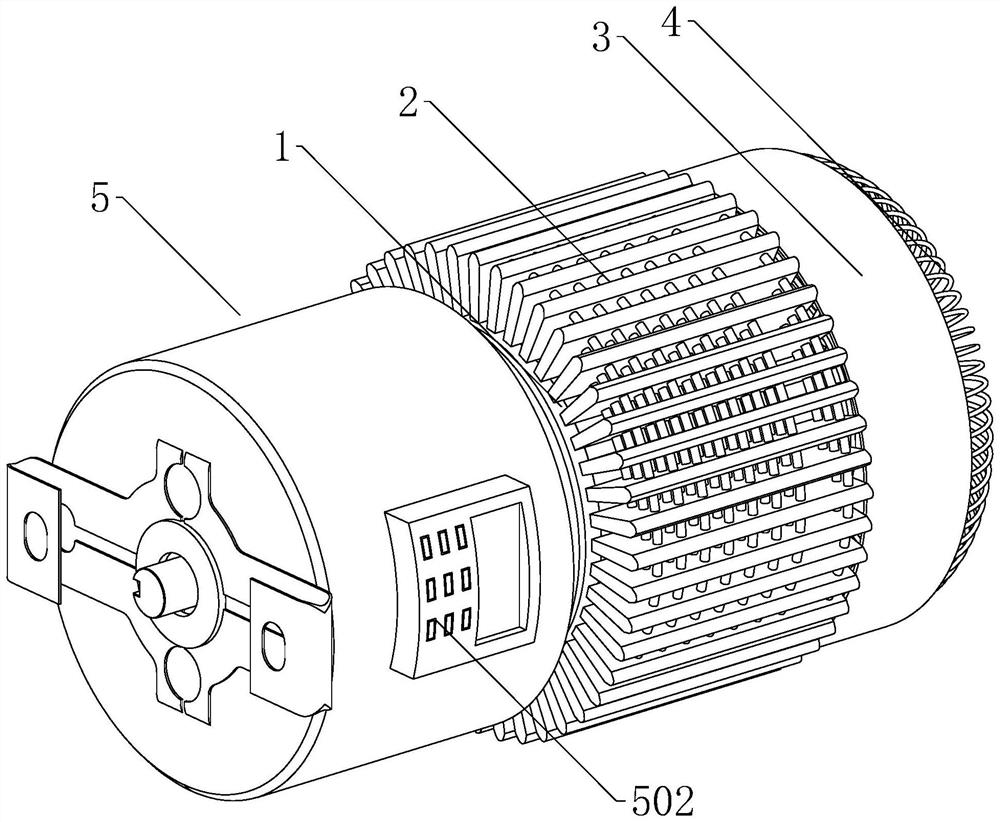
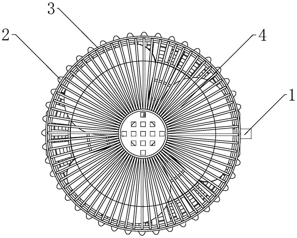
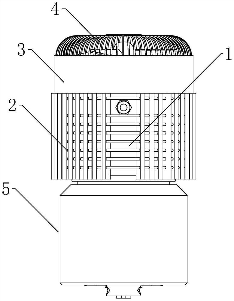
High-precision numerical control machine tool encoder

A technology of CNC machine tools and encoders, applied in the field of high-precision encoders, can solve problems such as discontinuous square waves, encoder failures, and code disc pollution, and achieve good heat dissipation effects, large heat dissipation areas, and high heat exchange efficiency

Pending Publication Date: 2022-07-29
苏州一诺机器人有限公司
View PDF0 Cites 0 Cited by
  • Summary
  • Abstract
  • Description
  • Claims
  • Application Information

AI Technical Summary

Problems solved by technology

[0002] Existing encoders are divided into optical encoders, magnetic encoders, and capacitive encoders. Among them, optical encoders have higher measurement accuracy, but they are easily affected by the external environment, especially the internal pollution of the code disc by external dust and oil. A polluted code disc will cause the square wave to be discontinuous or completely lost, thus greatly affecting the reliability and accuracy of the encoder, and when in use, due to the use of the LED light source, heat will be generated, and the heat accumulation will cause the LED to Reduced lifetime of the light source leading to encoder failure
In addition, glass or plastic code discs are easily damaged by vibration or extreme temperature, and the impact of temperature on the encoder is more serious.

Method used


Image

  • High-precision numerical control machine tool encoder
  • High-precision numerical control machine tool encoder
  • High-precision numerical control machine tool encoder

Examples


Embodiment Construction

[0021] The technical solutions in the embodiments of the present invention will be described clearly and completely below in conjunction with the embodiments of the present invention. Obviously, the described embodiments are only a part of the embodiments of the present invention, rather than all the embodiments. Embodiments, all other embodiments obtained by those of ordinary skill in the art without creative efforts, all belong to the protection scope of the present invention.

[0022] In order to facilitate the understanding of the present invention, the present invention will be more fully described below with reference to the related drawings, and several embodiments of the present invention are given. However, the present invention can be implemented in many different forms, and is not limited to Examples, rather, these examples are provided so that this disclosure will be thorough and complete.

[0023] It should be noted that when an element is referred to as being "fi...


PUM


Abstract

The invention relates to the technical field of high-precision encoders, in particular to a high-precision numerical control machine tool encoder which comprises an encoder body, a heat dissipation ring piece is arranged on the outer wall of the encoder body, a fixed shell is installed on the outer wall of the heat dissipation ring piece, and a heat dissipation fan is installed on the inner wall of the fixed shell. According to the encoder, the heat dissipation effect is better through the arrangement of the heat dissipation ring pieces of an annular structure, air cooling heat dissipation cooling is conducted on the encoder through the heat dissipation fan, stains are scraped off through the oil scraping plate, the stains adhere to the outer wall of the oil scraping plate, and finally the stains fall onto the inner wall of the inner shell; the oil suction block adsorbs oil dirt on the outer wall of the bearing, then the laser generator generates laser to irradiate the laser receiver, when the laser receiver cannot receive the laser due to oil dirt shielding, the laser receiver generates an electric signal and transmits the electric signal to the controller through the wire, and the controller lifts the accumulated oil dirt in the inner shell to be replaced and cleaned in time. And the practicability is better.

Description

technical field [0001] The invention relates to the technical field of high-precision encoders, in particular to a high-precision numerical control machine tool encoder. Background technique [0002] Existing encoders are divided into optical encoders, magnetic encoders and capacitive encoders. Among them, optical encoders have high measurement accuracy, but they are easily affected by the external environment, especially the external dust and oil contaminate the code disk internally. Contaminated code disc will cause the square wave to be discontinuous or completely lost, thus greatly affecting the reliability and accuracy of the encoder, and when in use, heat will be generated due to the use of the LED light source, and the heat accumulation will cause the LED The life of the light source is shortened, resulting in encoder failure. In addition, glass or plastic code discs are easily damaged by vibration or extreme temperature, and the effect of temperature on the encoder ...

Claims


Application Information

Patent Timeline
IPC IPC(8): B23Q17/24B23Q11/12B08B1/00B08B1/02F26B5/16
CPCB23Q17/24B23Q11/126F26B5/16B08B1/20B08B1/165
Inventor 李印戴竞豪庞承朋张燕妮
Owner 苏州一诺机器人有限公司
Why Eureka
Try Eureka