
Adjustable pintle injector and rocket engine

A technology of injectors and pintles, which is applied in the field of adjustable pintle injectors and rocket engines, can solve the problems that the atomization effect of the propellant is difficult to keep stable, and the high-efficiency combustion of the combustion chamber is difficult to achieve, so as to meet the requirements of stable combustion. Effect

Active Publication Date: 2022-07-29
东方空间(西安)宇航技术有限公司 +2
View PDF8 Cites 1 Cited by
  • Summary
  • Abstract
  • Description
  • Claims
  • Application Information

AI Technical Summary

Problems solved by technology

In order to meet the needs of structural adjustment, traditional pintle injectors are mostly designed as two-component coaxial annular nozzles, which are essentially straight-line injectors. The atomization form of the propellant is impact atomization. During the flow adjustment process However, due to the influence of the structural accuracy of the injector and the atomization form, it is difficult to maintain a stable propellant atomization effect, and it is difficult to achieve high-efficiency combustion in the combustion chamber within the full range of operating conditions.

Method used


Image

  • Adjustable pintle injector and rocket engine
  • Adjustable pintle injector and rocket engine

Examples


Embodiment Construction

[0037] Exemplary embodiments of the present disclosure will be described in more detail below with reference to the accompanying drawings. While exemplary embodiments of the present disclosure are shown in the drawings, it should be understood that the present disclosure may be embodied in various forms and should not be limited by the embodiments set forth herein. Rather, these embodiments are provided so that the present disclosure will be more thoroughly understood, and will fully convey the scope of the present disclosure to those skilled in the art.

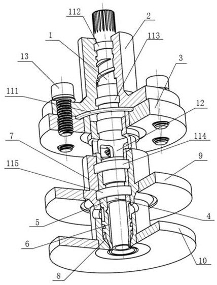
[0038] like figure 1 and figure 2 As shown, embodiments of the present invention provide an adjustable pintle injector, comprising:

[0039] Displacement lever 1;

[0040] The upper end cover 2 is sleeved on the displacement control rod 1, and the first end of the upper end cover 2 is screwed and connected with the first end of the displacement control rod 1; the upper end cover A displacement cavity is formed between t...


PUM


Abstract

The invention provides an adjustable pintle inspirator and a rocket engine. The adjustable pintle inspirator comprises a displacement control rod, an adjustable pintle inspirator body and an adjustable pintle inspirator body, the displacement control rod is sleeved with the upper end cover, and the first end of the upper end cover is connected with the first end of the displacement control rod in a screwed mode; a displacement cavity is formed between the second end part of the upper end cover and the second end part of the displacement control rod; the injector upper bottom sleeves the second end part of the upper end cover and is fixedly connected with the second end part of the upper end cover; the air nozzle is coaxial with the displacement control rod and is positioned below the second end part of the displacement control rod; the first end part of the liquid nozzle sleeves the second end part of the displacement control rod and is fixedly connected with the displacement control rod, the second end part of the liquid nozzle sleeves the gas nozzle, and an inner rotational flow cavity is formed between the second end part of the liquid nozzle and the gas nozzle; and the nozzle mounting seat sleeves the second end part of the liquid nozzle, and an outer rotational flow cavity is formed between the nozzle mounting seat and the liquid nozzle. According to the scheme, the injection pressure drop of the injector in the engine throttling process can be adjusted, and the phenomenon that the pressure drop is sharply increased along with flow increase is relieved.

Description

Technical field [0001] The invention relates to the field of rocket engines, and in particular to an adjustable needle injector and a rocket engine. Background technique [0002] In recent years, with the continuous development of recyclable rocket technology, higher and higher requirements have been placed on the thrust adjustment capabilities of liquid rocket engines. Through engine thrust adjustment, the power requirements such as overload control, ballistic optimization, and recovery control during rocket launch are met. In this process, the flow rate of the liquid rocket engine changes with the thrust. For a traditional fixed-structure injector, as the propellant flow rate increases (decreases), the injector pressure drop increases rapidly as the square of the flow rate. (reduce). When the engine thrust adjustment range is large, the injection pressure drop of this type of injector will change significantly, which is not conducive to stable combustion in the thrust ch...

Claims


Application Information

Patent Timeline
IPC IPC(8): F02K9/52
CPCF02K9/52
Inventor 韩亚威布向伟黄帅李军佟显义
Owner 东方空间(西安)宇航技术有限公司
Learn More