
Variable stiffness adjusting method of motor mount and motor mount thereof

An adjustment method and variable stiffness technology, applied in the direction of electric power devices, power devices, mechanical equipment, etc., to achieve the effect of ensuring vibration isolation, ensuring reliability and avoiding friction

Pending Publication Date: 2022-07-29
BOGE RUBBER&PLASTICS ZHUZHOU CO LTD
View PDF6 Cites 0 Cited by
  • Summary
  • Abstract
  • Description
  • Claims
  • Application Information

AI Technical Summary

Problems solved by technology

[0006] None of the above solutions can effectively balance the reliability and comfort of use. Therefore, inventing a method to adjust the variable stiffness of the structure has great practical significance and economic value in actual use.

Method used


Image

  • Variable stiffness adjusting method of motor mount and motor mount thereof
  • Variable stiffness adjusting method of motor mount and motor mount thereof
  • Variable stiffness adjusting method of motor mount and motor mount thereof

Examples


Embodiment 1

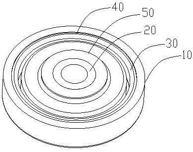
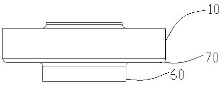
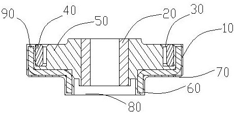
[0037] like figure 1 - Figure 4 As shown, this embodiment redesigns the structure of the motor mount according to different requirements for the lateral stiffness of the motor mount in actual application conditions. Specifically, the motor mount includes a rigid structure 90, and the rigid structure 90 includes a set of The stopper portion 10 at the open end of the motor suspension and the mounting portion 60 on the side away from the open end of the motor suspension; the stopper portion 10 and the mounting portion 60 are connected by the bearing portion 70 ; the rigid structure 90 is stepped as a whole. The mandrel 20 extends from the stopper portion 10 into the mounting portion 60 .

[0038] In this embodiment, a stopper portion 10 is added to the motor suspension structure, and a variable stiffness adjusting slot 30 is added at the stopper portion 10 , which can effectively adjust the stiffness of the elastic body 50 . The motor mount can choose an elastic material with ...

Embodiment 2

[0047] This embodiment discloses the variable stiffness adjustment method of the motor mount of Embodiment 1. In this embodiment, a gap portion 80 is provided between the bottom surface of the mounting portion 60 and the bottom plane of the mandrel 20 . When the entire suspension structure is press-fitted, a part of the elastic body 50 can be deformed and press-fitted into the void portion 80, so that the preloading effect of the entire upper and lower cushion blocks is good. The design of the gap 80 makes the height difference between the bottom of the mandrel 20 and the mounting part 60 before the product is installed, so that a concave space is formed in the mounting part 60; after installation, the height between the bottom of the mandrel 20 and the mounting part 60 The difference is eliminated, that is, a pre-stress is provided to the product to improve the service life of the product.

[0048] The variable stiffness adjustment method of the motor suspension of this embod...


PUM


Abstract

The invention belongs to the technical field of motor driving, and discloses a variable stiffness adjusting method of a motor mount, the motor mount comprises a rigid structure body and an elastic body borne in the rigid structure body, and a variable stiffness adjusting groove is longitudinally arranged close to the opening end of the inner wall of the rigid structure body; the variable stiffness adjusting groove provides transverse and vertical deformation spaces for an elastic body of the motor suspension; when the elastic body is subjected to vertical acting force, the elastic body adjusts the vertical rigidity and the transverse rigidity of the motor suspension through the supporting effect of the rigid structural body and the position limiting effect of the adjusting groove. The use and structural characteristics of a product are comprehensively considered, the motor suspension is divided into three parts, the stop part, the mounting part and the bearing part are combined, the variable-stiffness adjusting groove is formed in the stop part, and a space for stiffness deformation is provided for an elastic body of the motor suspension when the elastic body is stressed.

Description

technical field [0001] The invention belongs to the technical field of motor drive, and in particular relates to a variable stiffness adjustment method of a motor mount and a motor mount thereof. Background technique [0002] The motor mount is an important part of the motor-driven vehicle, in which the motor is mounted on the motor mounting intermediate plate, and the motor mounting intermediate plate is mounted on the vehicle through the bolt assembly. A rubber spacer is arranged between the component and the motor installation intermediate plate, so as to buffer the lateral displacement impact and vertical displacement impact of the motor installation intermediate plate. However, due to the shearing effect of the motor installation intermediate plate on the rubber pad, it is easy to cause cracking and damage, and the service life is low. [0003] Generally, the motor is mounted in pairs. In order to reduce vibration, the upper and lower pads are mostly rubber bodies. Whe...

Claims


Application Information

Patent Timeline
Patent Type & Authority Applications(China)
IPC IPC(8): F16F1/38B60K1/00
CPCF16F1/3863B60K1/00F16F2228/066
Inventor 焦黎明王继托钟海兵尹庆
Owner BOGE RUBBER&PLASTICS ZHUZHOU CO LTD
Learn More