

Data transmission cable and electronic system
A data transmission and electronic system technology, applied in cables, circuits, electrical components, etc., can solve problems such as poor signal integrity, improve quality and signal integrity, and solve the effect of limited transmission distance
- Summary
- Abstract
- Description
- Claims
- Application Information
AI Technical Summary
Problems solved by technology
Method used
Image

Examples
Embodiment 1
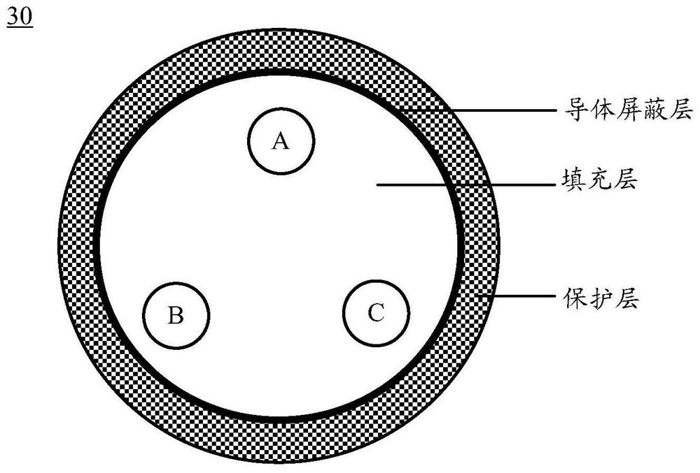
[0078] like image 3 As shown, the shape of the cross section of the data transmission cable 30 perpendicular to the length direction is flat, and the data transmission cable 30 includes a plurality of signal lines and power lines 303; On the cross section perpendicular to the length direction, they are arranged along the first direction; the plurality of signal lines and power lines 303 extend along the length direction of the data transmission cable 30 . The plurality of signal lines include a first differential pair 301 , a control signal line 302 and a clock signal line 304 . The data transmission cable 30 further includes a second medium filling layer 305 filled between the plurality of signal lines and between the plurality of signal lines and the power line 303, and wraps the plurality of signal lines and power lines in turn from the inside to the outside 303 and the second conductor shielding layer 306 and insulating protective layer 307 of the second dielectric filli...
Embodiment 2
[0124] The main difference between the second embodiment and the first embodiment is that the first embodiment includes one differential pair, namely the first differential pair 301, and the second embodiment includes two types of differential pairs, namely the first differential pair 301 and the second differential pair. A differential pair 301 and a second differential pair transmit signals in different directions.
[0125] like Image 6 As shown, the shape of the cross section of the data transmission cable 30 perpendicular to the length direction is flat, and the data transmission cable 30 includes a plurality of signal lines and power lines 303; On the cross section perpendicular to the length direction, they are arranged along the first direction; the plurality of signal lines and power lines 303 extend along the length direction of the data transmission cable 30 . The plurality of signal lines include a first differential pair 301 , a second differential pair 310 , a c...
Embodiment 3
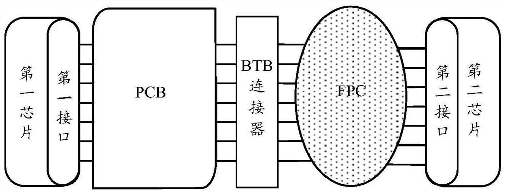
[0160] like Figure 11 As shown, the electronic system 100 provided by the embodiment of the present application includes a first chip 10 , a second chip 20 , a data transmission cable 30 , a first printed circuit board 40 and a second printed circuit board 50 . The first end of the data transmission cable 30 is electrically connected to the first printed circuit board 40 by welding; the first interface 101 of the first chip 10 is electrically connected to the first printed circuit board 40 by welding, thereby realizing the data transmission cable The first end of 30 is electrically connected to the first interface 101 . The second end of the data transmission cable 30 is electrically connected to the second printed circuit board 50 by welding; the second interface 201 of the second chip 20 is electrically connected to the second printed circuit board 50 by welding, thereby realizing the data transmission cable The second end of 30 is electrically connected to the second inte...
PUM
| Property | Measurement | Unit |
|---|---|---|
| length | aaaaa | aaaaa |
| thickness | aaaaa | aaaaa |
Abstract
Description
Claims
Application Information