Supercharge Your Innovation With Domain-Expert AI Agents!

Thickness compensation during cutting and bending

A bending and laser cutting technology, applied in the field of automation systems, can solve problems such as difficult and difficult to cut parts

Pending Publication Date: 2022-07-29
BYSTRONIC LASER
View PDF2 Cites 0 Cited by
  • Summary
  • Abstract
  • Description
  • Claims
  • Application Information

AI Technical Summary

Problems solved by technology

This means that even if an operator has access to state-of-the-art equipment, it is difficult to cut the part as required within all set tolerances
Also, it's more difficult to do so without generating any waste

Method used


Image

  • Thickness compensation during cutting and bending
  • Thickness compensation during cutting and bending
  • Thickness compensation during cutting and bending

Examples


Embodiment Construction

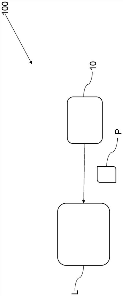
[0075] figure 1 An automation system 100 according to an embodiment of the third aspect of the invention is schematically illustrated.

[0076] exist figure 1In the embodiment shown in , the planner 10 has access to a machining machine, in particular a laser cutting machine L and / or a bending machine B. The planner 10 may be configured as a stand-alone electronic device. In an embodiment, the planner 10 is part of the processing machine L. The planner 10 may be connected to the processing machine L via a communication connection. Communication connections may include serial communication connections, such as Ethernet, CAN bus, and / or RS-485. The planner 10 is configured to calculate at least one auxiliary machining plan P for the workpiece to be machined by the machining machine L. In order to calculate the auxiliary machining plan P, several parameters are considered individually or in different combinations. The workpiece properties considered may include the thickness...


PUM


Abstract

The invention relates to a computer-implemented method and a planner for calculating at least one auxiliary machining plan for a workpiece to be machined by a machining machine. The method comprises the following steps: measuring the workpiece performance including the thickness parameter of the workpiece; at least one auxiliary machining plan is provided, the auxiliary machining plan being specific for the measured workpiece performance. As a result of the invention, a measurement of the workpiece performance is performed before starting machining the workpiece. Therefore, time and materials can be saved, and waste and waste can be reduced.

Description

technical field [0001] The present invention relates to a computer-implemented method and a planner for calculating at least one auxiliary machining plan for a workpiece to be machined, and to an automation system. Background technique [0002] The present invention focuses on metal processing, especially on sheet metal processing. Cutting and bending are important tasks in the metalworking industry. For best results, the physical properties of the process as well as the properties of the metal must be considered. Cutting is the partial or complete separation of an object or system into two or more pieces. By carefully programming and applying cutting parameters to the cutting machine, by achieving good tolerance values ​​as well as good edge quality, sheet metal can be quickly and precisely cut into two or more pieces. Due to inaccuracies in the manufacturing process of the metal sheet, the properties of the metal sheet may vary. In the case of altered performance, the ...

Claims


Application Information

Patent Timeline
IPC IPC(8): G05B19/401B23K26/38
CPCG05B19/401B23K26/38G05B2219/37398G05B2219/36199G05B2219/45041Y02P90/02G05B19/4155G05B2219/35519
Inventor 格里特·格里森维尔弗里德·利埃加尔
Owner BYSTRONIC LASER
Features
  • R&D
  • Intellectual Property
  • Life Sciences
  • Materials
  • Tech Scout
  • Unparalleled Data Quality
  • Higher Quality Content
  • 60% Fewer Hallucinations
Learn More