Fountain type brewing device capable of automatically feeding water
A self-filling fountain and brewing technology, which is applied in the field of brewing devices, can solve the problems of uneven brewing and inconvenience, and achieve the effect of uniform brewing
- Summary
- Abstract
- Description
- Claims
- Application Information
AI Technical Summary
Problems solved by technology
Method used
Image
Examples
Embodiment 1
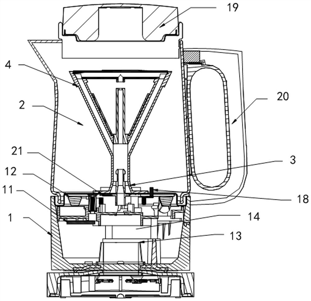
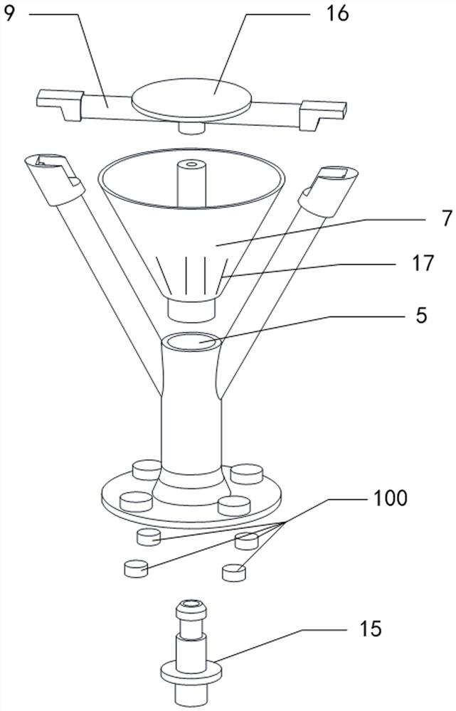
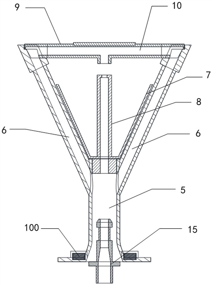
[0023] Embodiment 1, a self-filling fountain type brewing device provided in this embodiment includes a body 1, and the body 1 is provided with a brewing container 2 and is located in the brewing container 2 and is installed with a brewing rack 4 through a locking member 3, The brewing rack 4 is provided with a main flow channel 5 and at least one branch channel 6 communicating with the main flow channel 5, the brewing rack 4 is placed with a brewing basket 7, and the water outlet 8 of the main flow channel 5 is placed in the brewing basket 7, The brewing rack 4 is located above the brewing basket 7 and is provided with a guide rod 9 , and the guide rod 9 is provided with a guide cavity 10 that communicates with the branch channel 6 . The water pipe port 8, the body 1 is provided with a circuit board 11, a heating plate 12, a power connector 13 and a water pump 14, the heating plate 12, the power connector 13 and the water pump 14 are all electrically connected to the circuit b...
Embodiment 2
[0032] Example 2, as Figure 4 As shown, in order to facilitate the brewing of coffee, a coffee basket 101 is sleeved on the periphery of the brewing rack 4, the bottom of the coffee basket 101 is sleeved on the brewing rack 4, the brewing basket 7 is placed inside the coffee basket 101, and The upper end of the coffee basket 101 is overlapped with the cavity of the brewing container 2, so that when brewing coffee, the coffee powder is first brewed through the above-mentioned fountain, and then filtered through the coffee basket 101 to meet the requirements of brewing coffee. .
Embodiment 3
[0033] Example 3, as Figure 5 As shown, the tributary channel 6 in Embodiment 1 is arranged on the inner wall of the body 1, and the diversion cavity 10 in Embodiment 1 is arranged on the lid 19. The tributary channel 6 and diversion cavity 10 in this embodiment are still maintained. Thus, when the water pump 14 pumps water, the water outlet of the water pump 14 is divided into two paths, one enters the branch channel 6 located on the inner wall of the body 1, and the other is placed in the main flow channel 5, and finally collides with each other.
PUM
 Abstract
Description
Claims
Application Information
 - R&D
- Intellectual Property
- Life Sciences
- Materials
- Tech Scout
- Unparalleled Data Quality
- Higher Quality Content
- 60% Fewer Hallucinations
Browse by: Latest US Patents, China's latest patents, Technical Efficacy Thesaurus, Application Domain, Technology Topic, Popular Technical Reports.
© 2025 PatSnap. All rights reserved.Legal|Privacy policy|Modern Slavery Act Transparency Statement|Sitemap|About US| Contact US: help@patsnap.com


