Steel plate punching machine

A punching machine and steel plate technology, applied in the field of steel plate processing, can solve problems such as low punching efficiency, large hole position deviation, and steel plate warpage, meet the requirements of flatness, reduce scrap plate rate, and small hole position deviation Effect

Pending Publication Date: 2022-08-02
广州军晟科技有限公司
View PDF0 Cites 0 Cited by
  • Summary
  • Abstract
  • Description
  • Claims
  • Application Information

AI Technical Summary

Problems solved by technology

[0003] There are some problems in the existing steel plate punching process. On the one hand, the punching machine for punching three-dimensional curved corrugated steel plate is usually single-needle punching, which needs to be punched at different positions by moving the steel plate. One hole, the punching efficiency of this method is low, the hole position deviation is large, and in order to reduce the friction force when the steel plate is moved frequently, more lubricating oil is used, the pollution is large, and more oil pollution is not conducive to the prevention of subsequent steel plates. corrosion construction
On the other hand, due to the deformation of steel plates such as warping and curling during the process of leaving the factory, transportation, storage, and handling, it is difficult to ensure the consistency of punching and subsequent forming, resulting in a high scrap rate in the production of three-dimensional curved corrugated steel plates

Method used


Image

  • Steel plate punching machine
  • Steel plate punching machine
  • Steel plate punching machine

Examples


Embodiment 1

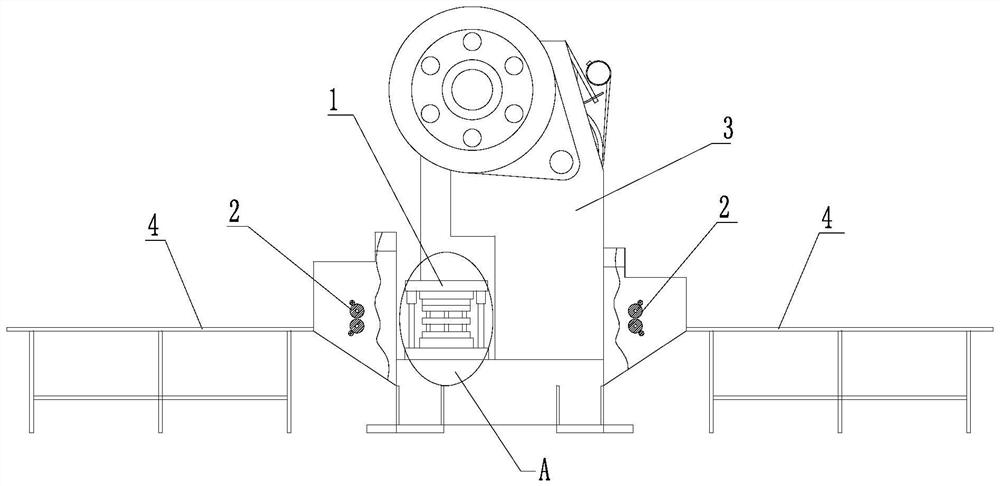
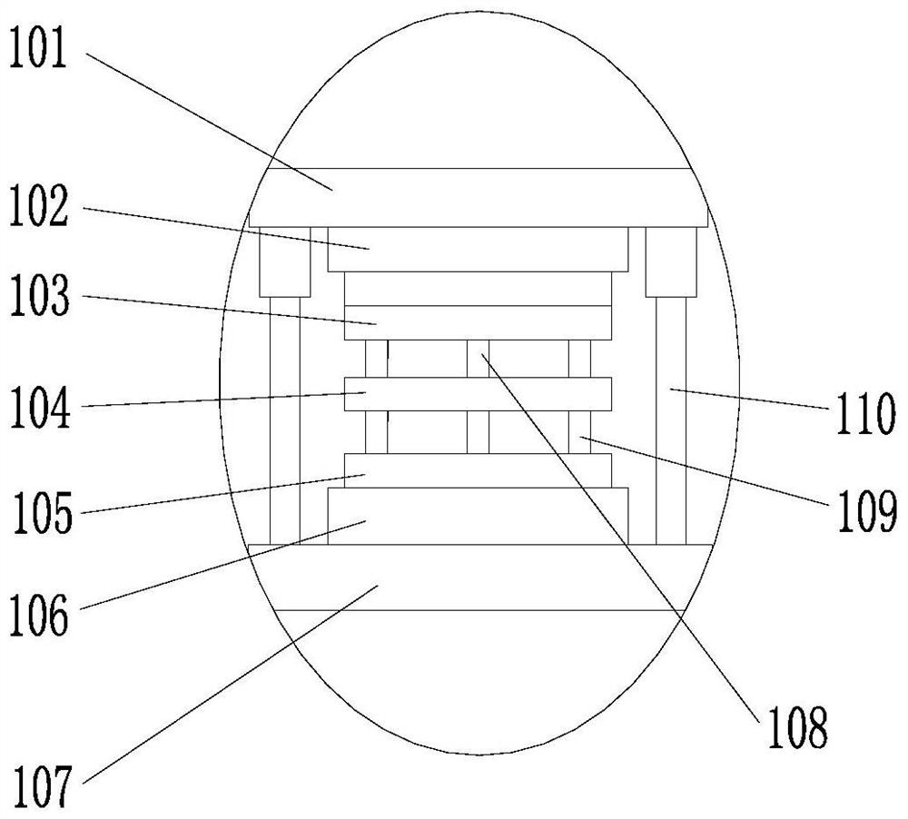
[0024] A steel plate punching machine includes a frame 3 and a punching device 1, the punching device is installed on the frame; the punching device includes a punching die, and the punching die includes an upper die base 102, an upper die assembly, a return plate 104, a lower die 105. The lower die base 106, the upper die assembly includes a stamping plate 103 and a punching needle 108, the upper die base, the stamping plate, the stripping plate, the lower die and the lower die base are arranged in order from top to bottom, and the stamping plate is fixedly connected to the upper The die base, the stripping plate is fixedly connected to the lower die, and the lower die is fixedly connected to the lower die base; a plurality of mounting holes are opened on the stamping plate, the mounting holes penetrate the stamping plate up and down, the number of punching pins is multiple, and the punching pins are connected through the mounting holes On the punching plate, the withdrawal pl...


PUM


Abstract

A steel plate punching machine comprises a machine frame and a punching device, and the punching device is installed on the machine frame. The stamping device comprises a stamping die, the stamping die comprises an upper die base, an upper die assembly, a material returning plate, a lower die and a lower die base, the upper die assembly comprises a stamping plate and a stamping needle, the upper die base, the stamping plate, the material returning plate, the lower die and the lower die base are sequentially arranged from top to bottom, the stamping plate is fixedly connected with the upper die base, the material returning plate is fixedly connected with the lower die, and the lower die is fixedly connected with the lower die base; a plurality of mounting holes are formed in the punching plate, the mounting holes vertically penetrate through the punching plate, the punching needles are connected with the punching plate through the mounting holes, and a material returning hole is formed in the material returning plate; the punching needle is in clearance fit with the punching plate, the upper surface of the punching plate is in sliding connection with a plurality of check blocks, the check blocks are controlled by an air cylinder, and when the check blocks are located above the installation holes, the punching needle is fixed under the limitation of the installation holes and the check blocks, so that the number of punched holes can be adjusted by controlling the positions of the check blocks, and therefore whole-row punching with the adjustable number is achieved.

Description

technical field [0001] The invention relates to the field of steel plate processing, in particular to a steel plate punching machine. Background technique [0002] Three-dimensional curved corrugated steel plate is widely used in large building structures due to its advantages of high strength, good stability and adjustable curvature. Drill holes in the steel plate. [0003] There are some problems in the existing steel plate punching process. On the one hand, the punching machine for punching the three-dimensional curved corrugated steel plate is usually a single-pin punching, and the punching at different positions needs to be carried out by moving the steel plate. One hole, this method has low punching efficiency, large hole position deviation, and in order to reduce the friction force when the steel plate is frequently moved, more lubricating oil is used, and the pollution is large, and more oil pollution is not conducive to the prevention of subsequent steel plates. C...

Claims


Application Information

Patent Timeline
Patent Type & Authority Applications(China)
IPC IPC(8): B21D28/26B21D28/34B21D1/02
CPCB21D28/26B21D28/34B21D1/02Y02P70/10
Inventor 李利晟薛红萍黄江黄新华冯增富范德友朱开冯碧玉陈猛叶土林王建宇
Owner 广州军晟科技有限公司
Why Eureka
Try Eureka