Auxiliary loading device for ceramic wine bottle production

A loading device and ceramic wine bottle technology, which is applied in biological packaging, transportation and packaging, and packaging item types, etc., can solve the problems of increasing damage to ceramic wine bottles, shaking of the workbench, and inconvenient use, so as to improve the effect of limit fixation, Guaranteed stability and easy operation

Pending Publication Date: 2022-08-02
深圳卓上品牌设计顾问有限公司
View PDF0 Cites 0 Cited by
  • Summary
  • Abstract
  • Description
  • Claims
  • Application Information

AI Technical Summary

Problems solved by technology

[0003] Most of the existing ceramic wine bottles are often carried by workers during the production process, which will increase the damage of ceramic wine bottles during transportation, and at the same time, some mechanical loading devices will perform more intense operations when transporting ceramic wine bottles , it is easy to cause the table to shake, which indirectly increases the collision damage of the ceramic wine bottle during transportation, causing inconvenience in use

Method used


Image

  • Auxiliary loading device for ceramic wine bottle production
  • Auxiliary loading device for ceramic wine bottle production
  • Auxiliary loading device for ceramic wine bottle production

Examples


Embodiment 1

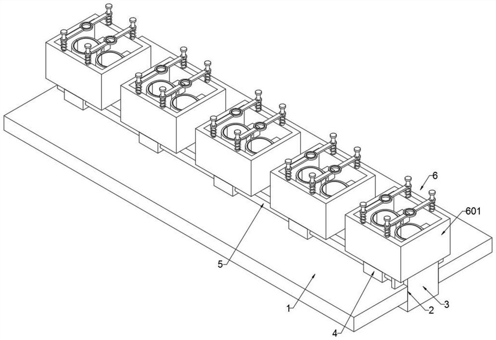
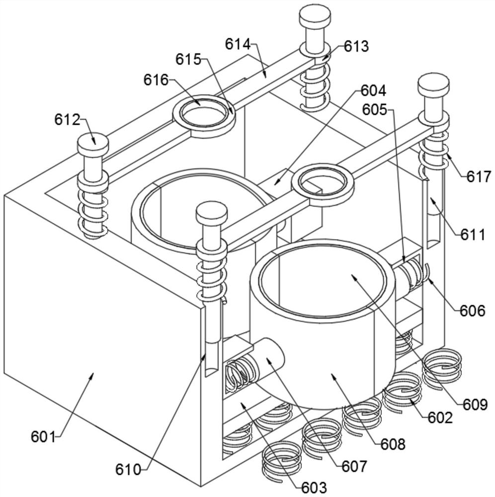
[0023] see Figures 1 to 2 , in the embodiment of the present invention, an auxiliary loading device used in the production of ceramic wine bottles, including a transfer table 1, a transport mechanism 6 and a transfer mechanism 7, the transfer table 1 is provided with a through slot 2, and the through slot 2 The transmission plate 3 is slidably connected. The front and rear ends of the transmission plate 3 are provided with a number of first limit blocks 4 . Position rod 5, the upper end of the first limit block 4 is provided with a transport mechanism 6, and the lower end of the transfer table 1 is provided with a transport mechanism 7, the transport mechanism 6 is fixed by a box 601, a first spring 602, a buffer plate 603, Block 604, groove 605, second spring 606, connecting rod 607, splint 608, first protective pad 609, positioning groove 610, sliding rod 611, limit plate 612, connecting ring 613, connecting plate 614, limit ring 615 , a second protective pad 616 and a thi...

Embodiment 2

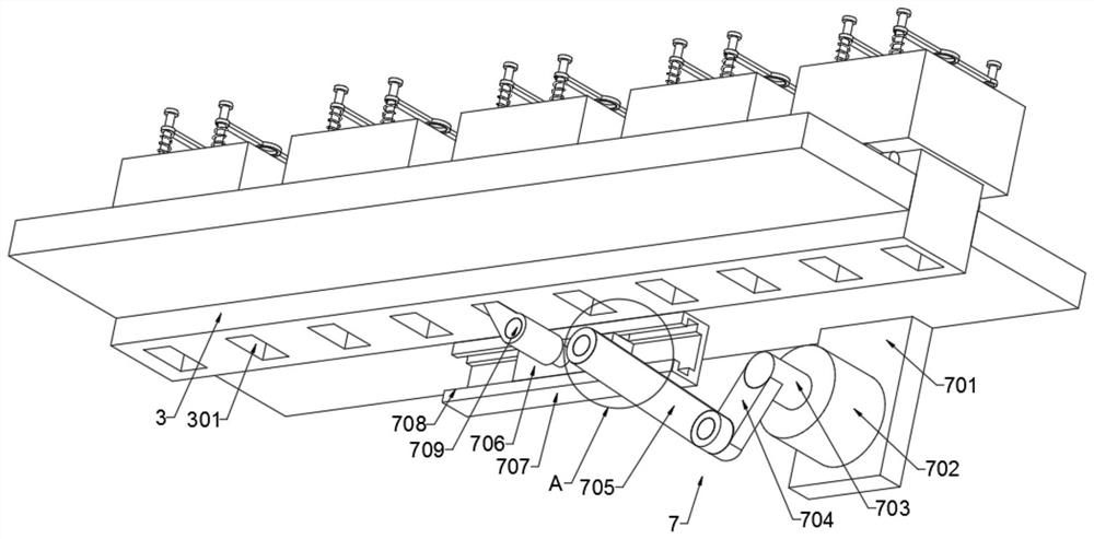
[0025] see Figures 3 to 4In the embodiment of the present invention, the transmission mechanism 7 consists of a fixed plate 701, a motor 702, a rotating shaft 703, a fixed rod 704, a movable rod 705, a slider 706, a connection block 707, a first limit slot 708, a push block 709, The second limit block 710 and the second limit slot 711 are formed. The upper end of the fixing plate 701 is fixedly connected to the conveying table 1 , the front end of the fixing plate 701 is provided with a motor 702 , and the front end of the motor 702 is provided with a rotating shaft 703 . A fixed rod 704 is provided, and the fixed rod 704 is movably connected to a movable rod 705, and the other end of the movable rod 705 is movably connected to a sliding block 706. The sliding block 706 is provided with a connecting block 707, and the upper end of the connecting block 707 is fixedly connected to the transfer table 1 , and the front end of the connecting block 707 is provided with a first limi...


PUM


Abstract

The auxiliary loading device comprises a conveying table, a conveying mechanism and a conveying mechanism, a through groove is formed in the conveying table, a conveying plate is slidably connected into the through groove, a plurality of first limiting blocks are arranged at the front end and the rear end of the conveying plate, and the lower ends of the first limiting blocks are attached to the conveying table; limiting rods are slidably connected to the first limiting blocks, a conveying mechanism is arranged at the upper ends of the first limiting blocks, and a conveying mechanism is arranged at the lower end of the conveying table. When the device is used, a motor is started to drive a rotating shaft to rotate, the rotating shaft drives a fixed rod to rotate, the fixed rod rotates to drive a movable rod to move, and then the movable rod drives a sliding block to reciprocate left and right on a connecting block; and the conveying plate can be conveniently driven to move in the horizontal direction, so that the conveying mechanism is driven to move the ceramic wine bottles, operation is easy, and personnel operation is facilitated.

Description

technical field [0001] The invention relates to the technical field of ceramic wine bottle production, in particular to an auxiliary loading device used in the production of ceramic wine bottles. Background technique [0002] Wine bottles are containers used to hold wine. Historically, wine bottles were mostly presented to the world in a simple style of "soy sauce bottle style", glass material, less information, and no heavy decoration. Nowadays, glass wine bottles play the leading role in my country, and ceramic wine bottles are used in large quantities (many wine bottles use Jingdezhen porcelain, Yixing purple sand and porcelain fired from well-known kilns), and a small number of them use aluminum, galvanized iron, plastic, Wine bottles made of stainless steel, artificial crystal, bamboo, wood, bamboo and special paper, etc., the wine bottles are more and more colorful, and there is a flourishing scene of flowers blooming, including glass wine bottles, plastic wine bottles,...

Claims


Application Information

Patent Timeline
IPC IPC(8): B65D25/10B65D25/02B65D81/05B65D85/44
CPCB65D25/101B65D25/02B65D81/05B65D85/44Y02W90/10
Inventor 武强
Owner 深圳卓上品牌设计顾问有限公司
Why Eureka
Try Eureka