[0040] The technical solutions in the embodiments of the present invention will be clearly and completely described below with reference to the accompanying drawings in the embodiments of the present invention; obviously, the described embodiments are only a part of the embodiments of the present invention; rather than all the embodiments. Based on the embodiments of the present invention; all other embodiments obtained by those of ordinary skill in the art without creative work; all belong to the protection scope of the present invention.
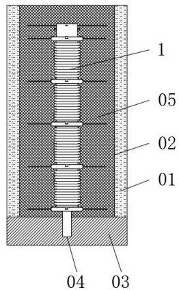
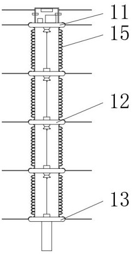
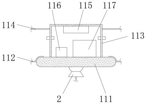
[0041] see Figure 1-13 , a road subgrade settlement detection device, comprising a subgrade main body 01, a fixed borehole 02 is opened on the top surface of the subgrade main body 01, a force-holding soil layer 03 is arranged at the bottom of the roadbed main body 01, and the top surface of the force-holding soil layer 03 is provided A fixed installation hole 04 is opened, and the fixed installation hole 04 shares the central axis with the fixed borehole 02. The inside of the fixed borehole 02 is filled with an expansive soil sealing body 05, and the bottom surface of the expansive soil sealing body 05 and the bearing soil layer 03 The top surface is fixedly connected, and the inside of the expansive soil sealing body 05 is provided with a subgrade settlement real-time monitor 1 .
[0042] The subgrade settlement real-time monitor 1 includes an upper monitoring part 11, a middle monitoring part 12, and a lower monitoring part 13. The upper monitoring part 11, the middle monitoring part 12, and the lower monitoring part 13 are arranged in order from top to bottom, and the number of the middle monitoring parts 12 is Three, the upper monitoring member 11, the middle monitoring member 12, and the lower monitoring member 13 are all provided with threading holes 14, between the upper monitoring member 11 and the middle monitoring member 12, and between the two adjacent middle monitoring members 12, An elastic corrugated pipe 15 is connected between the monitoring element 12 and the lower monitoring element 13, and the connection with the elastic corrugated pipe 15 can be connected by a detachable structure, such as threaded socket connection, movable clamping connection, etc., which is convenient to adjust according to the specific conditions of the formation The number of the middle monitoring pieces 12 and the length of the elastic bellows 15, the upper monitoring piece 11, the middle monitoring piece 12, the lower monitoring piece 13, and the elastic bellows 15 are all fixedly inserted into the inside of the expansive soil sealing body 05, and the upper monitoring piece 11. The middle monitoring part 12 , the lower monitoring part 13 , the elastic bellows 15 and the expansive soil sealing body 05 share the same central axis.
[0043] The upper monitoring part 11 includes an upper monitoring plate 111, which is fixedly embedded in the interior of the expansive soil sealing body 05, the bottom surface of the upper monitoring plate 111 is connected with the top end of the corresponding elastic bellows 15, and the side surface of the upper monitoring plate 111 is A first linkage grab bar 112 is fixedly connected, and the first linkage grab bar 112 is fixedly inserted into the inside of the expansive soil sealing body 05. A monitoring box 113 is fixedly connected to the top surface of the upper monitoring plate 111, and the monitoring box 113 can be disassembled. , the monitoring box 113 is fixedly embedded in the inside of the expansive soil sealing body 05, the side of the monitoring box 113 is fixedly connected with a second linkage grab bar 114, and the second linkage grab bar 114 is fixedly inserted in the expansive soil sealing body 05. Inside, a wireless transmitter 115 is fixedly connected to the top surface of the inner cavity of the monitoring box 113, a GPS locator 116 and an intelligent control processor 117 are fixedly installed on the bottom surface of the inner cavity of the monitoring box 113, and a side surface of the monitoring box 113 is fixedly connected with Wiring pipe, the intelligent control processor 117 is electrically connected with the wireless transmitter 115, the GPS locator 116, the conductive ring 342, the conductive arc panel 64, and the conductive member 62, the intelligent control processor 117, the conductive ring 342, and the L-row brush shrapnel 346 , The straight conductive sheet 344, the curved conductive sheet 349, and the resistance sheet 345 form an electrical circuit, and the intelligent control processor 117, the conductive arc panel 64, the conductive ring 65, the resistance wire 49, and the conductive member 62 form an electrical circuit.
[0044] The middle monitoring part 12 includes a middle monitoring plate 121, the upper and lower sides of the middle monitoring plate 121 are connected with the end of the elastic corrugated pipe 15, and the side surface of the middle monitoring plate 121 is fixedly connected with a third linkage grab bar 122, the middle monitoring plate 121, The third linkage grab bars 122 are all fixedly embedded in the interior of the expansive soil sealing body 05 .
[0045] The lower monitoring member 13 includes a lower monitoring plate 131, the top surface of the lower monitoring plate 131 is connected with the bottom end of the corresponding elastic corrugated pipe 15, the side surface of the lower monitoring plate 131 is fixedly connected with a fourth linkage gripping strip 132, the lower monitoring plate 131, The fourth linkage grab bars 132 are all fixedly embedded in the interior of the expansive soil sealing body 05. The bottom surface of the lower monitoring plate 131 is connected with a bottom fixing column 133. The connection method can be a detachable structure. The bottom fixing column 133 is fixed and inserted Connected to the inside of the fixed mounting hole 04, the bottom fixed post 133 may be an expansion nail.
[0046] A deflection monitoring mechanism 2 is provided on the bottom surfaces of the upper monitoring disk 111 and the middle monitoring disk 121 , and a displacement detection mechanism 4 is provided on the top surfaces of the middle monitoring disk 121 and the lower monitoring disk 131 .
[0047] The deflection monitoring mechanism 2 includes a fixed spherical hole 20 and a flip spherical shell 21. The number of fixed spherical holes 20 is multiple. The fixed spherical hole 20 is provided on the bottom surface of the upper monitoring plate 111 and the middle monitoring plate 121, and the flip spherical shell 21 is movably embedded. Installed in the inside of the fixed spherical hole 20, the bottom of the inverted spherical shell 21 is fixedly connected with a counterweight reducer 22, the inner wall of the inverted spherical shell 21 is fixedly connected with a fixed transverse arm 23, and the other end of the fixed transverse arm 23 is fixedly connected with a Inner spherical ring 24, a monitoring sphere 25 is embedded inside the inner spherical ring 24, the center of the monitoring sphere 25 coincides with the center of the inverted spherical shell 21, and a monitoring force at the bottom of the monitoring sphere 25 is fixedly connected on the surface of the monitoring sphere 25. The arm 26, the bottom end of the monitoring force arm 26 penetrates the counterweight reducer 22, and the monitoring force arm 26 is vertically downward.
[0048] It also includes a declination monitoring mechanism 3. The declination monitoring mechanism 3 includes an upper baffle plate 31 and a lower baffle plate 32. Both the upper baffle plate 31 and the lower baffle plate 32 are fixedly connected to the inner wall of the overturned spherical shell 21. The vertically upward ball radius on 21 is perpendicular to the upper baffle plate 31 and the lower baffle plate 32 at the same time, the upper baffle plate 31 is located above the lower baffle plate 32, and the lower baffle plate 32 is provided with a through hole 33 in the middle, Three magnetic ball position determination mechanisms 34 are arranged between the disk 31 and the lower baffle disk 32 . The three magnetic ball position determination mechanisms 34 are evenly distributed around the through hole 33 , and corresponding components 35 are arranged inside the through hole 33 .
[0049]The magnetic ball position determination mechanism 34 includes an insulating tube 341, and the number of the insulating tubes 341 is two. A conductive ring 342 is fixedly embedded on the surface, and an inversion cylinder 343 is movably connected between the two insulating tubes 341. The inversion cylinder 343 can rotate relative to the insulating tube 341, and a flat conductive sheet is fixedly embedded on the bottom surface of the inner cavity of the inversion cylinder 343. 344, the top surface of the inner cavity of the reversing cylinder 343 is fixedly embedded with a resistor sheet 345, and the right end of the bottom surface of the flat conductive sheet 344 and the right end of the top surface of the resistor sheet 345 are fixedly connected with L rows of brush shrapnel 346, L rows of brushes The other end of the shrapnel 346 extends to the outside of the reversing cylinder 343 and is slidably connected with the conductive ring 342 . The right side of the inner cavity of the reversing cylinder 343 is driven and connected with a determining piston 348 through the determining spring 347 , and the determining piston 348 slides with the inner wall of the inverting cylinder 343 Connect, determine that a curved conductive sheet 349 is fixedly connected to the left side of the piston 348, the bottom end of the curved conductive sheet 349 slides on the surface of the flat conductive sheet 344, and the top end of the curved conductive sheet 349 slides on the surface of the resistance sheet 345 , a magnetic column 340 is fixedly connected to the right side of the determination piston 348 , the right end of the magnetic column 340 passes through the determination spring 347 and extends to the outside of the inversion cylinder 343 , and the magnetic post 340 is movably inserted on the right side of the inversion cylinder 343 .
[0050] The corresponding component 35 includes a positioning cylinder 351, the bottom end of which is fixedly connected to the surface of the monitoring sphere 25, the positioning cylinder 351 and the monitoring force arm 26 share the same central axis and the central axis passes through the center of the monitoring sphere 25, the positioning cylinder The bottom surface of the inner cavity of 351 is connected with a jacking rod 353 through a jacking spring 352. The jacking rod 353 is slidably inserted into the interior of the positioning cylinder 351. The top of the lifting rod 353 extends to the outside of the positioning cylinder 351 and penetrates through the hole 33. And a strong magnetic sphere 354 is fixedly connected. The strong magnetic sphere 354 is slidably connected with the bottom surface of the upper baffle plate 31 and is matched with the magnetic column 340. The strong magnetic sphere 354 is initially located at the center of the bottom surface of the upper baffle plate 31. There is a magnetic attractive force between the magnetic column 340 and the strong magnetic sphere 354 when the strong magnetic ball 354 is in the center of the bottom surface of the upper baffle plate 31 has the same magnetic attractive force among the three magnetic columns 340 .
[0051] The displacement detection mechanism 4 includes a detection box 41 . The number of the detection boxes 41 is multiple. The detection boxes 41 are fixedly connected to the top surfaces of the middle monitoring plate 121 and the lower monitoring plate 131 , between the left and right sides of the inner cavity of the detection box 41 . The movable sleeve is connected with a rotating horizontal bar 42, and the external movable sleeve of the rotating horizontal bar 42 is connected with a power storage spring 43. The torque of the power storage spring 43 is large enough to make the resistance wire 49 and the monitoring force arm 26 stretched straight, and the storage spring One end of the force spring 43 is fixedly connected to the surface of the rotating cross bar 42, the other end of the force accumulating spring 43 is fixedly connected to the top surface of the inner cavity of the detection box 41, and two external movable sleeves of the rotating cross bar 42 are connected. The bearing vertical plate 44 is supported, and the bottom end of the bearing vertical plate 44 is fixedly connected to the bottom surface of the inner cavity of the detection box 41 , and a rotating ring 45 is movably embedded on the two sides of the two bearing vertical plates 44 that are close to each other. The rotating ring 45 and the rotating cross bar 42 share the same central axis, the surface of the rotating ring 45 is fixedly connected with a buffer spring 46, the buffer spring 46 is movably sleeved on the outside of the rotating cross bar 42, and the other end of the buffer spring 46 is fixedly connected with an insulating receiver. The winding roller 47, the outer surface of the insulating winding roller 47 is provided with a threaded groove, and the depth of the threaded groove is deeper. There is a drive bar 48, the drive bar 48 is adapted to the insulating winding roller 47, and a resistance wire 49 is wound on the outside of the insulating winding roller 47, and the resistance wire 49 is wound inside the thread groove in the form of a single strand, and the resistance wire 49 The other end extends to the outside of the detection box 41 and is fixedly connected to the end of the monitoring force arm 26 .
[0052] Also includes a positioning mechanism 5, the positioning mechanism 5 includes a positioning transverse plate 51, the positioning transverse plate 51 is fixedly connected between the two bearing vertical plates 44 and located below the insulating winding roller 47, and the top surface of the positioning transverse plate 51 is fixedly connected. There is a positioning block 52, an arc groove 53 is opened on the top surface of the positioning block 52, the arc groove 53 is movably buckled on the outside of the insulating winding roller 47, and the inner wall of the arc groove 53 is fixedly connected with a male thread Strip 54, the male thread strip 54 is adapted to the thread groove on the surface of the insulating winding roller 47, the radial length of the male thread strip 54 is less than the depth of the thread groove, and there is a winding between the male thread strip 54 and the thread groove. gap.
[0053] Also includes a length detection mechanism 6, the length detection mechanism 6 includes an L-shaped insulating support 61, an elastic telescopic rod 63 and a conductive ring 65, the L-shaped insulating support 61 is fixedly connected to the top surface of the inner cavity of the detection box 41, and the L-shaped insulating support The other end of 61 is fixedly connected with a conductive member 62, the conductive member 62 is movably sleeved on the outside of the resistance wire 49, the top end of the elastic telescopic rod 63 is fixedly connected to the top surface of the inner cavity of the detection box 41, and the bottom end of the elastic telescopic rod 63 is fixedly connected. The conductive arc panel 64 is fixedly connected, the conductive ring 65 is fixedly sleeved on the outside of the insulating winding roller 47 and is located at its left end, the outer surface of the conductive ring 65 is slidably connected with the conductive arc panel 64, and the other end of the resistance wire 49 It is electrically connected to the conductive ring 65 .
[0054] The conductive member 62 includes a conductive cylinder 621 , a vertical channel 622 is opened on the upper and lower surfaces of the conductive cylinder 621 , an insulating lining tube 623 is fixedly embedded in the vertical channel 622 , and a V is opened inside the conductive cylinder 621 The two ends of the V-shaped channel 624 are respectively connected with the two vertical channels 622. The resistance wire 49 runs through the insulating lining tube 623 and the V-shaped channel 624. The resistance wire 49 slides on the inner wall of the V-shaped channel 624, so that the resistance The wire 49 is in good contact with the conductive member 62 .
[0055] working principle:
[0056] First, drill a fixed hole 02 on the ground, so that the fixed hole 02 continues to extend downward until the surface of the bearing soil layer 03 is exposed, and then punch a fixed installation hole 04 on the surface of the bearing soil layer 03. The end fixing column 133 is fixedly inserted into the inside of the fixed installation hole 04, and then the lower monitoring plate 131 is fixedly installed on the top of the bottom end fixing column 133, and then the elastic bellows 15 is installed on the top surface of the lower monitoring plate 131. The middle monitoring piece 12 is installed on the top of the elastic bellows 15 , then the second elastic bellows 15 is installed on the top surface of the middle monitoring piece 12 , and then the second middle monitoring piece is installed on the top of the second elastic bellows 15 12, then install the third elastic bellows 15 on the top surface of the second middle monitoring piece 12, then install the third middle monitoring piece 12 on the top of the third elastic bellows 15, and then install the third middle monitoring piece 12 on the top of the third elastic bellows 15. A fourth elastic bellows 15 is installed on the top surface of the middle monitoring member 12, and then a monitoring member 11 is installed on the top of the fourth elastic bellows 15, and then expansive soil is filled into the fixed borehole 02 and compacted. Until only the upper monitoring part 11 is outside the expansive soil, then dig out the cable ditch connected to the fixed borehole 02 on the ground, then put the power cable in the cable ditch, then open the monitoring box 113 and make the power cable Connect to the intelligent control processor 117, then put the monitoring box 113 back to its original position, then close the cable ditch and fill the fixed hole 02 with expansive soil. At this time, the upper monitoring element 11 is also buried in the expansive soil. The expansive soil forms the expansive soil sealing body 05 inside the fixed borehole 02, so far the installation is completed, and then the subgrade main body 01 settles under the influence of various factors, and then the subgrade main body 01 is carried by the expansive soil sealing body 05 for monitoring. After the middle monitoring member 12 and the lower monitoring member 13, between the upper and lower adjacent middle monitoring members 12, and between the middle monitoring member 12 and the upper monitoring member 11, the distance between the middle monitoring member 12 and the upper monitoring member 11 is At the same time, the elastic bellows 15 is compressed and shortened, and then the rotating horizontal bar 42 rotates under the action of the torsion of the power storage spring 43, and then the rotating horizontal bar 42 rotates with the insulating winding roller 47 through the transmission bar 48, and then the resistance wire 49 is wound into the thread groove on the outside of the insulating winding roller 47. At the same time, the insulating winding roller 47 moves to the left under the action of the thread fit between the thread groove and the male thread strip 54, which is used to assist the resistance. The wire 49 is wound to the inside of the thread groove on the insulating take-up roller 47, and then the number of resistance wires 49 wound on the outside of the insulating take-up roller 47 increases, the length increases, and then the current passing through the resistance wire 49 will decrease, and then the intelligent control processor 117 Calculate the length change of the resistance wire 49 wound outside the insulating winding roller 47 according to the current value, the length change between the lower monitoring member 13 and the first middle monitoring member 12 is A, the first middle monitoring member 12 and the second middle monitoring member The length change between the monitoring pieces 12 is B, the length change between the second middle monitoring piece 12 and the third middle monitoring piece 12 is C, and the length change between the third middle monitoring piece 12 and the upper monitoring piece 11 The quantity is D, in the When lateral displacement occurs, the settlement amount of the soil layer corresponding to the first middle monitoring element 12 is A, the settlement amount corresponding to the soil layer of the second middle monitoring element 12 is A plus B, and the third middle monitoring element 12 corresponds to the settlement of the soil layer. The amount is A plus B plus C, and the settlement amount of the soil layer corresponding to the upper monitoring piece 11 is A plus B plus C plus D. When the subgrade main body 01 is laterally displaced, the upper monitoring piece 11 and the middle monitoring piece 12 will carry The deflection monitoring mechanism 2 is laterally offset relative to the displacement detection mechanism 4 immediately below it, so that the resistance wire 49 is inclined and the monitoring force arm 26 is pulled laterally, so that the monitoring force arm 26 is inclined, and then the monitoring force arm 26 passes through The monitoring ball 25 deflects laterally with the corresponding component 35, and then the corresponding component 35 is inclined, and then the jacking rod 353 slides on the ground of the upper baffle plate 31 with the strong magnetic ball 354 under the action of the elastic repulsion of the jacking spring 352, Then the strong magnetic sphere 354 deviates from the center position on the bottom surface of the upper baffle plate 31, and then the magnetic attraction force of the strong magnetic sphere 354 to the three magnetic columns 340 changes, and the magnetic column 340 in the offset direction of the strong magnetic sphere 354 is subjected to an increased force. Then the magnetic column 340 moves to the right end of the straight conductive sheet 344 by pulling the curved conductive sheet 349 by the determination piston 348, and then the length of the resistance sheet 345 connected to the circuit becomes shorter and the current becomes larger, and then the intelligent control processor 117 calculates according to the magnitude of the current. The distance value between the strong magnetic sphere 354 and the magnetic column 340 is calculated, and then the distance between the strong magnetic sphere 354 and the central axis of the insulating tube 341 is calculated. The force of the magnetic column 340 in the other direction is reduced, and the corresponding judgment piston 348 is in the corresponding judgment. Under the action of the elastic force of the spring 347, the corresponding curved conductive sheet 349 moves to the left, and then the length of the corresponding resistance sheet 345 connected to the circuit increases, and the current becomes smaller. The intelligent control processor 117 calculates according to the current magnitude. The distance between the central axes of the tubes 341, then the intelligent control processor 117 uses the three-point positioning principle to infer the orientation of the strong magnetic sphere 354 and its distance from the initial position, and then monitor the distance from the strong magnetic sphere 354 at the initial position. The distance from the center of the sphere 25 is fixed, and the intelligent control processor 117 can infer the angle of the corresponding component 35 and monitor the offset of the force arm 26 according to the trigonometric function. The actual settlement distance and offset distance, and then the intelligent control processor 117 obtains the specific positioning through the GPS locator 116, and then the intelligent control processor 117 wirelessly transmits the positioning information and detection information to the receiving terminal through the wireless transmitter 115.
[0057] The above is only a preferred embodiment of the present invention; but the protection scope of the present invention is not limited to this; any person skilled in the art is within the technical scope disclosed by the present invention; according to the technical solution of the present invention Equivalent replacement or change with its improved concept; all should be covered within the protection scope of the present invention.