
Supporting structure for ammeter detection device and detection method

A detection device and support structure technology, which is applied in the direction of measuring devices, measuring device casings, and measuring electrical variables, etc., can solve the problems of small use range, cumbersome operation, and easy danger caused by electrified current needles, and achieve the effect of improving safety

Pending Publication Date: 2022-08-02
STATE GRID JIANGSU ELECTRIC POWER CO LTD MARKETING SERVICE CENT +1
View PDF2 Cites 1 Cited by
  • Summary
  • Abstract
  • Description
  • Claims
  • Application Information

AI Technical Summary

Problems solved by technology

[0003] Prior art document 1 (CN102565467B) discloses a detection pin device for electric energy meters, including a detection platform, a support frame fixed on the detection platform, a longitudinal transfer mechanism arranged on the support frame, terminal blocks, a drive control module, The test module, wherein the terminal block includes a terminal block, a current needle and a signal needle, the disadvantage of the prior art document 1 is that the power supply structure of the current needle and the signal needle is not explained, if the direct connection of the wires in the prior art is used to realize the power supply , the current needle is charged throughout the whole process, which is easy to cause danger, and can only be used for electric energy meters with a specific number of connections, and the scope of use is small
The disadvantage of the prior art document 2 is that it is necessary to develop an assembly line to increase the economic cost of the meter detection; the arrangement and combination of the terminals is limited, and if it is necessary to adapt to the newly added connection holes of other combinations, it is necessary to re-add the connection terminals at different intervals. cumbersome operation

Method used


Image

  • Supporting structure for ammeter detection device and detection method
  • Supporting structure for ammeter detection device and detection method
  • Supporting structure for ammeter detection device and detection method

Examples


Embodiment Construction

[0024] The specific embodiments of the present invention will be further described below with reference to the accompanying drawings. It should be noted here that the descriptions of these embodiments are used to help the understanding of the present invention, but do not constitute a limitation of the present invention. In addition, the technical features involved in the various embodiments of the present invention described below can be combined with each other as long as they do not conflict with each other.

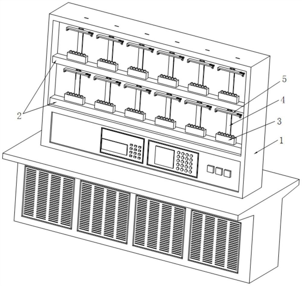
[0025] The present invention provides such as figure 1 The shown support structure for an electric meter detection device includes a detection table 1, a wiring box 2 is installed on the detection table 1, the wiring box 2 is made of aluminum alloy, and the inner wall corners are provided with multiple reinforcing ribs to avoid bending. In some cases, a conductive wire and a lifting motor control wire are arranged in the wiring box 2, the conductive wire is connected...


PUM


Abstract

The invention discloses a supporting structure for an ammeter detection device and a detection method, and the supporting structure comprises a detection platform, the detection platform is provided with a wiring box, the upper end of the wiring box is provided with a plurality of ammeter supporting seats at equal intervals, the upper ends of the ammeter supporting seats are provided with a plurality of insertion columns, each insertion column is of a hollow structure, and the interior of each insertion column is provided with a liftable power connection column. According to different types of ammeters, the power connection columns of different combinations are lifted, and the power connection columns are inserted into wiring holes in the bottoms of the ammeters; and after the test is finished, the power connection column drops and is disconnected with the detected ammeter. According to the supporting structure for the electricity meter detection device, the lifting electricity connection columns are arranged, the electricity connection columns matched with the electricity connection holes in the electricity meter phase in number can be connected according to different types of electricity meters, the supporting structure is very convenient, does not need manual replacement, is convenient and safe, and when the electricity connection columns are not completely lifted, the electricity connection columns are not electrified, so that the safety is further improved.

Description

technical field [0001] The invention belongs to the technical field of electric meter detection, and in particular, relates to a support structure and a detection method for an electric meter detection device. Background technique [0002] The electric energy meter test bench is a device with the function of testing the calibration constant of the watt-hour meter. The installation of the electric meter of the existing electric meter test bench is relatively simple. To detect the difference of the electric meter, it is necessary to increase or decrease the number of the connection poles. The existing detection table is to increase or decrease the connection poles by disassembling and assembling, which is very troublesome. [0003] Prior art document 1 (CN102565467B) discloses an electric energy meter detection pin device, comprising a detection table, a support frame fixed on the detection table, a longitudinal transfer mechanism arranged on the support frame, a connection te...

Claims


Application Information

Patent Timeline
IPC IPC(8): G01R35/04G01R1/04
CPCG01R35/04G01R1/04G01R1/0408
Inventor 高雨翔王舒蔡奇新穆卓文季欣荣李悦周玉夏宇航宋瑞鹏高凡邵雪松
Owner STATE GRID JIANGSU ELECTRIC POWER CO LTD MARKETING SERVICE CENT
Learn More