Novel airborne power supply system of multi-rotor unmanned aerial vehicle

A technology for a multi-rotor unmanned aerial vehicle and a power supply system, which is applied in the field of the airborne power supply system of a new type of multi-rotor unmanned aerial vehicle, can solve the problems of a single energy supply method, troublesome battery replacement, short battery life, etc., and achieves extended battery life and replacement. Fast, convenient and safe

Active Publication Date: 2016-08-10
南京创凯航空科技有限公司
View PDF8 Cites 1 Cited by
  • Summary
  • Abstract
  • Description
  • Claims
  • Application Information

AI Technical Summary

Problems solved by technology

[0003] Multi-rotor UAV is a kind of UAV. Multi-rotor UAV has the advantages of compact structure, small size, flexible movement and stable flight. It is widely used in civilian and military applications, and is popular with the public; Rotor UAVs are also facing many problems at present, such as: (1) the battery life is short, which directly determines the flight stability and application of multi-rotor UAVs; (2) the fixed position of the battery is inconvenient. For the fixing of the battery, the man-machine often directly binds the battery to the lower end of the frame with straps. This way of fixing the battery is likely to cause the battery to fall off during flight, and the fixing position of the battery is not easy to determine, which directly affects the flight balance of the multi-rotor UAV. problem, and it is not safe; (3) Battery replacement is troublesome. At present, the battery replacement of multi-rotor drones is performed manually, which takes up the time of the flight operator to a large extent; (4) Energy supply method Single, the existing multi-rotor drones mostly use lithium batteries for power supply

Method used


Image

  • Novel airborne power supply system of multi-rotor unmanned aerial vehicle
  • Novel airborne power supply system of multi-rotor unmanned aerial vehicle
  • Novel airborne power supply system of multi-rotor unmanned aerial vehicle

Examples


Embodiment Construction

[0024] In order to make the technical means, creative features, goals and effects achieved by the present invention easy to understand, the present invention will be further described below in conjunction with specific illustrations.

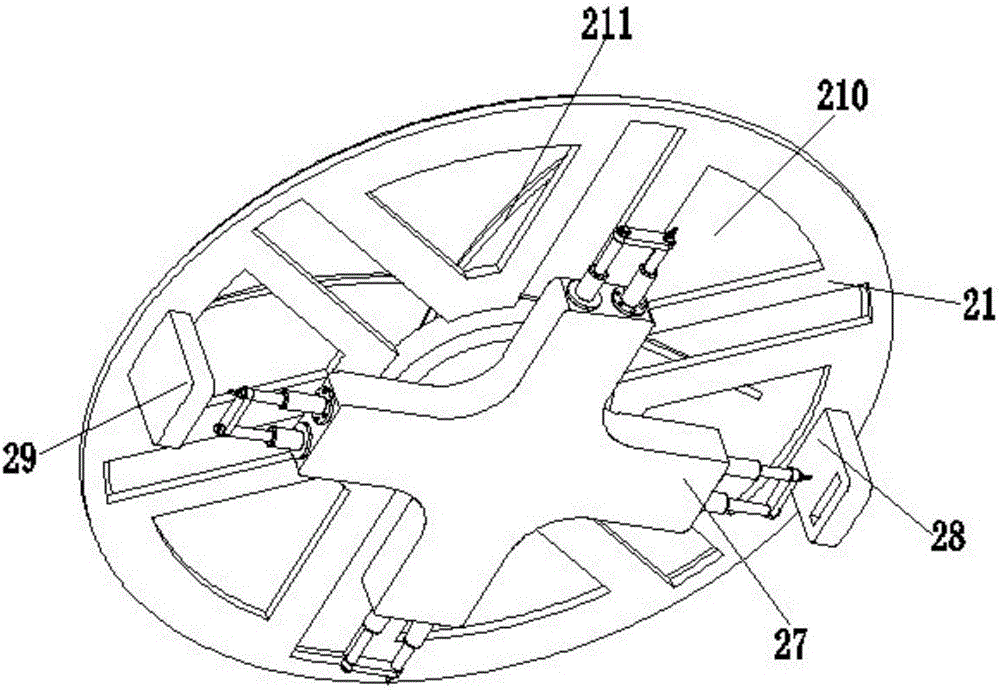
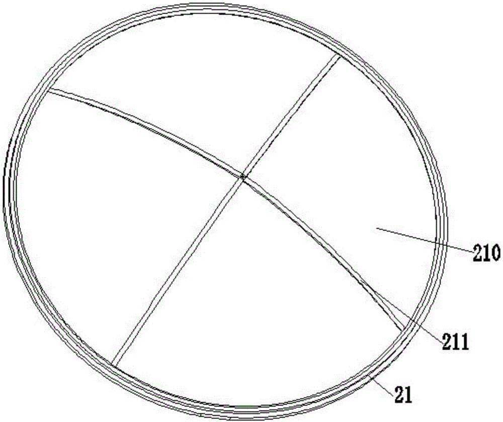
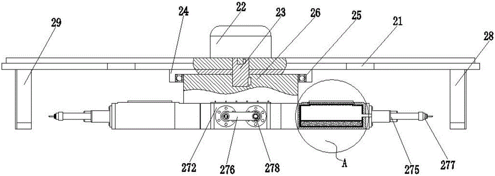
[0025] Such as Figure 1 to Figure 7 As shown, a new type of multi-rotor UAV airborne power supply system includes a fixed frame 21, a rotating motor 22, a rotating shaft 23, a sleeve 24, a bearing 25, a turntable 26, a battery distribution device 27, a power supply stand 28, and a charging stand 29 , solar panel 210 and clip 211; the fixed frame 21 is a disc-shaped structure, and the upper end surface of the fixed frame 21 is provided with an annular collar, and the fixed frame 21 is provided with a fan-shaped material reduction port, and the material of the fixed frame 21 adopts The carbon fiber material is integrally formed at one time. The carbon fiber material has the advantages of high axial strength and modulus, low density, high specific...


PUM


Abstract

The invention relates to a novel airborne power supply system of a multi-rotor unmanned aerial vehicle. The novel airborne power supply system comprises a fixing frame, a rotary motor, a rotary shaft, a sleeve cylinder, a bearing, a rotary table, a battery distributing device, a power supply seat, a charging seat, a solar cell panels and clamp strips, wherein the rotary motor is arranged at the center of the fixing frame, and a main shaft of the rotary motor is connected with the upper end of the rotary shaft through keys; the lower end of the rotary shaft is connected with the upper end of the sleeve cylinder through keys; the rotary table is positioned at the lower end of the sleeve cylinder, the battery distributing device is positioned just under the rotary table, the power supply seat is positioned at the right lower part of the fixing frame, the charging seat is positioned at the left lower part of the fixing frame, and the solar cell panel is positioned above the fixing frame. The novel airborne power supply system has the advantages that the solar cell panelsisare used for converting solar energy into electric energy in the flight process, and the electric energy is supplied to the novel airborne power supply system, so that the enduration time is prolonged; the function of automatically replacing batteries in turn is realized by the battery distributing device, the manual replacement is not needed, the replacement is rapid and convenient, the balance property of battery fixing is good, and the safety is high.

Description

technical field [0001] The invention relates to the field of aircraft auxiliary accessories, in particular to a novel multi-rotor UAV airborne power supply system. Background technique [0002] UAV is an unmanned aircraft controlled by radio remote control equipment and self-contained program control device. From a technical point of view, it can be divided into unmanned helicopter, unmanned fixed-wing aircraft, unmanned multi-rotor aircraft, unmanned airship and unmanned aircraft. UAVs can be divided into military and civilian use according to the application field, and military UAVs are divided into reconnaissance aircraft and target drones; at present, UAVs can be widely used in national ecological environment protection, aerial photography, surveying and mapping, mineral resources Exploration, disaster monitoring, traffic patrol, power line inspection, public security monitoring, emergency disaster reduction, emergency command, artificial rainfall, national defense secur...

Claims


Application Information

Patent Timeline
Patent Type & Authority Applications(China)
IPC IPC(8): B64D27/24B64C27/08
CPCB64C27/08B64D27/24B64D2211/00B64U50/34B64U50/19Y02T50/50Y02T50/60
Inventor 郑琳琳
Owner 南京创凯航空科技有限公司
Why Eureka
Try Eureka