Feeding device suitable for esophageal cancer patient
A technology for esophageal cancer and patients, which is applied to the field of feeding devices for patients with esophageal cancer, can solve the problems of cumbersome liquid feeding work, inconvenient production, etc., and achieve the effects of avoiding physical health, reducing burden, and promoting appetite.
- Summary
- Abstract
- Description
- Claims
- Application Information
AI Technical Summary
Problems solved by technology
Method used
Image
Examples
specific Embodiment approach 1
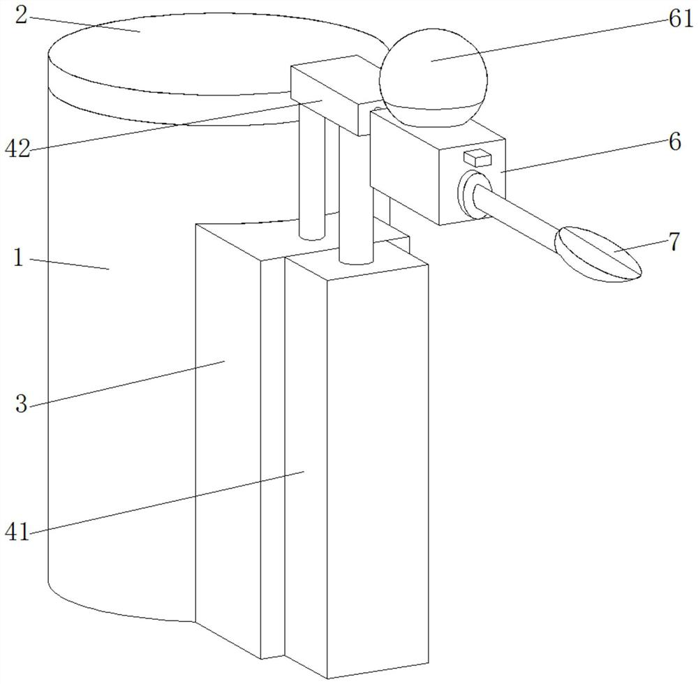
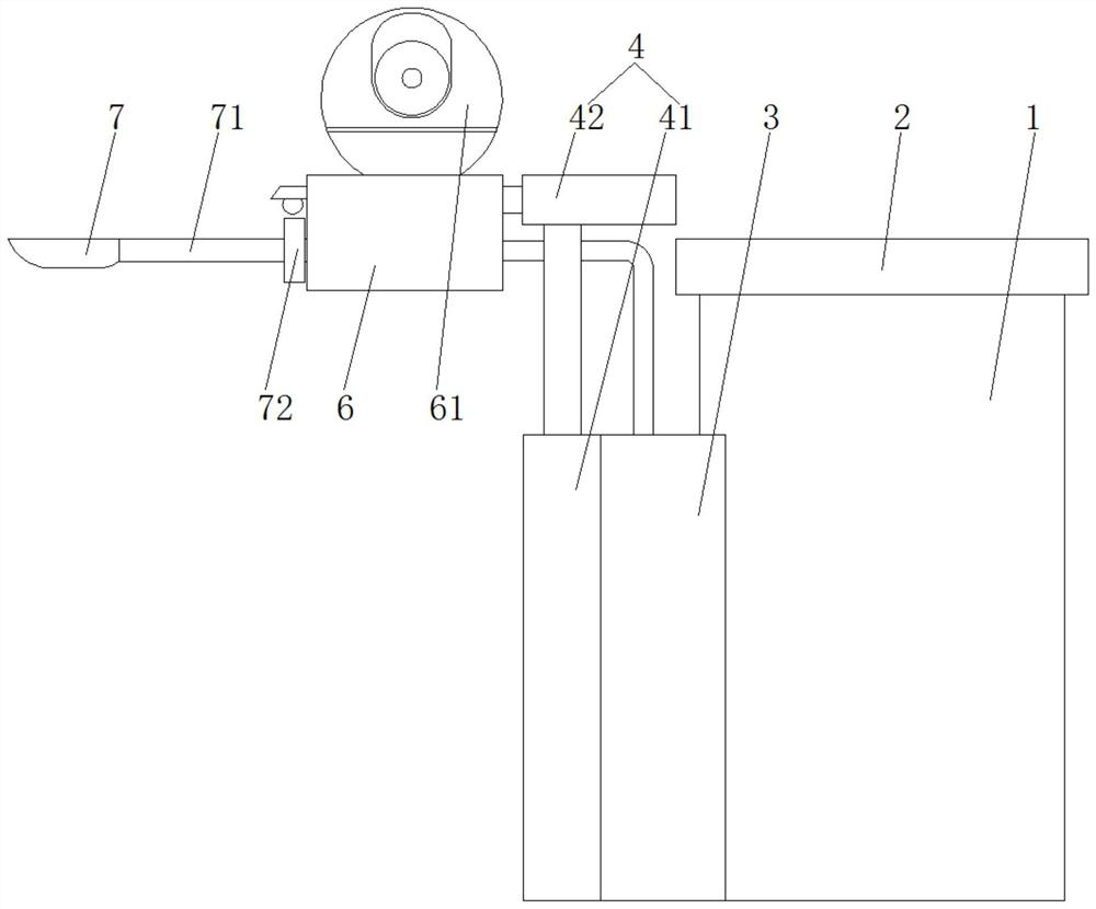
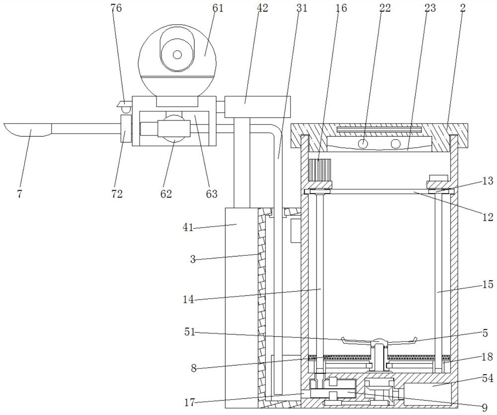
[0040] Specific implementation mode 1: Please refer to Figure 1-8 , the present invention provides a technical scheme: a feeding device suitable for patients with esophageal cancer, comprising:
[0041] The crushing cylinder 1, the inner wall of the crushing cylinder 1 is provided with a lug plate 11, the two lug plates 11 are respectively inserted with a driving shaft 14 and a driven shaft 15, and the driving shaft 14 and the driven shaft 15 are both sleeved with a first gear 13 and screw sleeve 18;
[0042] The cylinder cover 2 is withheld on the top of the crushing cylinder 1, the bottom surface of the cylinder cover 2 is provided with a circular groove 24 and a ring groove 27, and a disinfection lamp 22 and a concave lens 23 are installed inside the circular groove 24;
[0043] The heating box 3, the heating plate 32 is installed on the inner wall of the heating box 3, and the heating box 3 communicates with the crushing cylinder 1 through the discharge port 17;
[0044...
specific Embodiment approach 2
[0053] Embodiment 2: This embodiment is a further limitation of Embodiment 1, such as figure 1 , image 3 and Figure 4 As shown, the bottom end of the side of the crushing cylinder 1 is provided with a discharge port 17, the outer side of the crushing cylinder 1 is provided with a temperature sensor 33, and the temperature sensor 33 is located in the heating box 3, the top of the crushing cylinder 1 is inserted into the ring groove 27, the ear plate A ring gear 12 is installed on the inner wall of the crushing cylinder 1 below 11. The inner tooth surface of the ring gear 12 meshes with the first gear 13. The lug 11 is used to connect the driving shaft 14 and the driven shaft 15. The first motor 16 drives the driving The rotation of the shaft 14 makes the first gear 13 on the driving shaft 14 rotate, the first gear 13 drives the ring gear 12 to rotate, and the ring gear 12 drives the first gear 13 on the driven shaft 15 to rotate, thereby making the driven shaft 15 rotate.
specific Embodiment approach 3
[0054] Embodiment 3: This embodiment is a further limitation of Embodiment 2, such as image 3 , Figure 4 and Image 6 As shown, the lug plate 11 is screwed together with the screw sleeve 18, and a first motor 16 is installed on the top surface of the left lug plate 11. The first motor 16 drives the driving shaft 14 to rotate, and the driving shaft 14 passes through the ring gear 12 and the first motor 16 to rotate. A gear 13 drives the driven shaft 15 to rotate, the driving shaft 14 and the driven shaft 15 pass through the filter screen 8, and the threaded sleeve 18 performs a linear slide table movement along the driving shaft 14 and the driven shaft 15. When the threaded sleeve 18 moves upward, the threaded sleeve 18 18 drives the limit ring 82 to move upward, so that the filter screen 8 moves upward to realize the filter residue effect.
PUM
 Abstract
Description
Claims
Application Information
 - R&D
- Intellectual Property
- Life Sciences
- Materials
- Tech Scout
- Unparalleled Data Quality
- Higher Quality Content
- 60% Fewer Hallucinations
Browse by: Latest US Patents, China's latest patents, Technical Efficacy Thesaurus, Application Domain, Technology Topic, Popular Technical Reports.
© 2025 PatSnap. All rights reserved.Legal|Privacy policy|Modern Slavery Act Transparency Statement|Sitemap|About US| Contact US: help@patsnap.com


