
Device and method for inhibiting flying dust in construction process of building engineering

A technology of construction engineering and installation box, applied in the field of dust suppression in construction, can solve the problems of inconvenient automatic all-round spraying, affecting the effect of spraying and dust reduction, and reducing the service life of nozzles, so as to save the need for regular cleaning or replacement and avoid dust reduction. Not in place, the effect of guaranteeing the service life

Active Publication Date: 2022-08-05
中城投荣欣(浙江)建设集团有限公司
View PDF3 Cites 0 Cited by
  • Summary
  • Abstract
  • Description
  • Claims
  • Application Information

AI Technical Summary

Problems solved by technology

[0005] Aiming at the deficiencies of the prior art, the present invention provides a device and method for suppressing dust in the construction process of a construction project, which solves the problem that the existing device for suppressing the dust in the construction process of a construction project has a limited range when spraying water mist and is inconvenient. Automatic all-round spraying, and the exposure of the nozzle to the outside during spraying will easily cause the hole in the nozzle to be blocked, which will easily affect the effect of subsequent spraying and dust reduction, and the subsequent manual replacement of the nozzle will be required, reducing the use of the nozzle The problem of longevity

Method used


Image

  • Device and method for inhibiting flying dust in construction process of building engineering
  • Device and method for inhibiting flying dust in construction process of building engineering
  • Device and method for inhibiting flying dust in construction process of building engineering

Examples


Embodiment 1

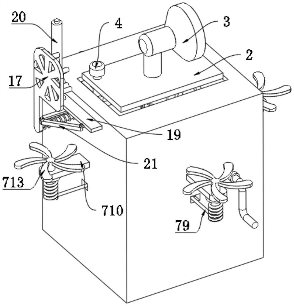
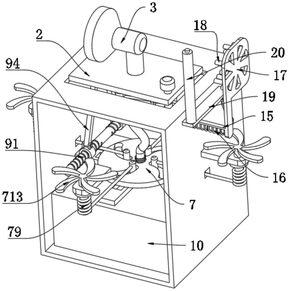
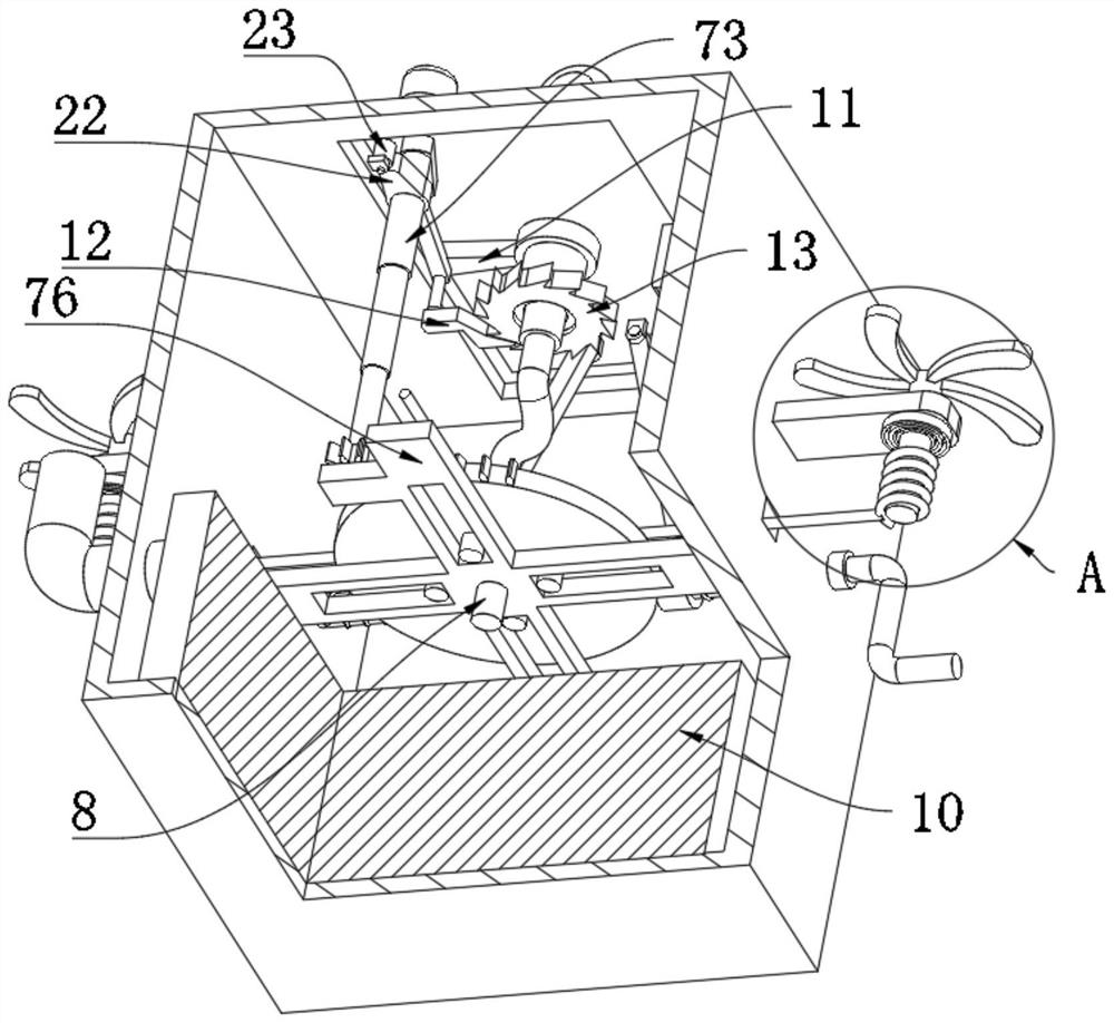
[0043] see figure 1 to and image 3 and Figure 5 , including the installation box 1, the inner cavity wall of the installation box 1 is slidably connected to the support plate 2 through the sliding groove and the slider, the upper end surface of the support plate 2 is rotatably connected with the spray head 3, and the upper end surface of the support plate 2 is fixedly connected with a small motor 4 , the output shaft of the small motor 4 penetrates the lower end surface of the support plate 2 and is fixedly connected with a crank 5, the inner cavity wall of the installation box 1 is installed with a diffusion mechanism 7, the inner cavity wall of the installation box 1 is installed with a lifting mechanism 9, and the cavity wall of the installation box 1 is installed with a lifting mechanism 9. The bottom is fixedly connected with a water tank 10, and the inner cavity wall of the water tank 10 is connected with a water pipe 8 through a water pump. A ratchet wheel 13 is fix...

Embodiment 2

[0046] see figure 1 and figure 2 , the right side wall of the installation box 1 is slidably connected with the vertical plate 17 through the sliding rod 15, the inner side wall of the vertical plate 17 is fixedly connected with the cleaning head 18, the upper end surface of the sliding rod 15 is rotatably connected with the wheel 23, the right side of the installation box 1 A spring telescopic rod 16 is fixedly connected to the side wall, and the right end of the spring telescopic rod 16 is fixedly connected to the lower end surface of the vertical plate 17 .

[0047] When working, through the cooperation of the sliding rod 15, the spring telescopic rod 16, the vertical plate 17, the cleaning head 18, the cam 22 and the runner 23, when the small motor 4 rotates, the cam 22 will also be driven to rotate. When the cam 22 rotates to the right When the rotating wheel 23 slides to the right, the vertical plate 17 slides to the right through the sliding rod 15 and stretches the s...

Embodiment 3

[0049] see figure 1 and figure 2 , the right side wall of the installation box 1 is slidably connected with a sliding plate 19, the upper end face of the sliding plate 19 is rotatably connected with an installation shaft, the outer wall of the installation shaft is inserted with a sponge roller 20, and the right side wall of the sliding plate 19 is rotatably connected with a connecting rod 21, connecting One end of the rod 21 away from the sliding plate 19 is rotatably connected with the side wall of the vertical plate 17 .

[0050] During operation, through the cooperation of the sliding plate 19, the installation shaft, the sponge roller 20 and the connecting rod 21, when the vertical plate 17 slides inward, it will rotate by squeezing the connecting rod 21, thereby driving the sliding plate 19 to slide backward, so that the upper The sponge roller 20 slides backward and wipes the cleaning head 18 , which can scrape off the dust and sundries on the cleaning head 18 , keep ...


PUM


Abstract

The invention discloses a device for inhibiting flying dust in the construction process of building engineering, the device comprises a mounting box, the inner cavity wall of the mounting box is slidably connected with a supporting plate through cooperation of a sliding groove and a sliding block, the outer wall of a spray head is rotatably connected with a rotating plate, and the lower end face of the rotating plate is rotatably connected with a pawl through a pin shaft. The lower end face of the crank is rotationally connected with a rotating rod, and the end, away from the crank, of the rotating rod is rotationally connected with the pin shaft. The device for restraining dust raising in the building engineering construction process solves the problems that when an existing device for restraining dust raising in the building engineering construction process is used for spraying water mist, the range is limited; the problems that in the prior art, automatic all-dimensional spraying is inconvenient, the situation that when spraying is conducted, a spraying head is exposed outside, holes in the spraying head are prone to being blocked, the follow-up spraying dust falling effect is prone to being affected, and the service life of the spraying head is shortened due to the fact that the spraying head needs to be manually and periodically replaced in the follow-up process are solved.

Description

technical field [0001] The invention relates to the technical field of dust suppression during construction, in particular to a device and method for suppressing dust during construction of a building project. Background technique [0002] Construction site refers to the production activities in the implementation stage of the project. During the construction process, a lot of dust will be generated, which will affect the air quality and cause harm to the construction personnel. Some construction sites will use dust suppression devices to spray water mist to reduce dust. [0003] The existing devices for suppressing dust during construction of construction projects have a limited range when spraying water mist, which makes it inconvenient to automatically spray in all directions, and when the spray head is exposed to the outside, it is easy to cause the holes at the spray head to be blocked, which easily affects the follow-up. The effect of spraying and dust reduction, and t...

Claims


Application Information

Patent Timeline
Patent Type & Authority Applications(China)
IPC IPC(8): B01D47/06E04G21/00B08B9/04B08B1/00F16F15/067B05B3/02B05B12/18B05B15/16B05B15/522
CPCB01D47/06E04G21/00B08B9/04F16F15/067B05B3/02B05B12/18B05B15/16B05B15/522B08B1/143Y02B30/70
Inventor 刘军章俊冯丽君俞腾余秋红田秋红
Owner 中城投荣欣(浙江)建设集团有限公司
Learn More