Reciprocating type tool bit set

A cutter head group, reciprocating technology, applied in metal processing and other directions, can solve the problems of poor support of the outer cutter net, easy to break, inability to shave clean body hair, high manufacturing and assembly costs, and improve cutting stability and structure. Compact, long-standing effect

Pending Publication Date: 2022-08-05
浙江精博五金科技有限公司
View PDF0 Cites 0 Cited by
  • Summary
  • Abstract
  • Description
  • Claims
  • Application Information

AI Technical Summary

Problems solved by technology

[0002] The reciprocating cutter heads currently on the market generally cannot shave body hairs of different lengths with one cut. Two sets of knives are needed. One set of knives cuts the long hair first, and the other set of knives shaves the remaining short hair.
Equipping two cutter heads requires two cutting blades and corresponding drive mechanisms, which are not only heavy and more prone to wear than standard single-purpose utensils, but are also expensive to manufacture and assemble, and operating the combined device requires switching between modes , more time-consuming, often complex operation, quite uncomfortable experience
[0003] For the cutter head group itself, it generally includes the moving knife and the outer knife net. The outer knife net, that is, the outer net cover, generally remains motionless. Cleanliness refers to whether the cutting can be done thoroughly, the cutting comfort, and the life of the equipment, especially the cutter head. The first two require the outer knife net to be as thin as possible, but the thin outer knife net has poor support and is easy to break and has a short life
Therefore, the general outer knife screen can only achieve a thickness of 15 wires or even more than 15 wires in order to take into account the supporting force.

Method used


Image

  • Reciprocating type tool bit set
  • Reciprocating type tool bit set
  • Reciprocating type tool bit set

Examples


Embodiment Construction

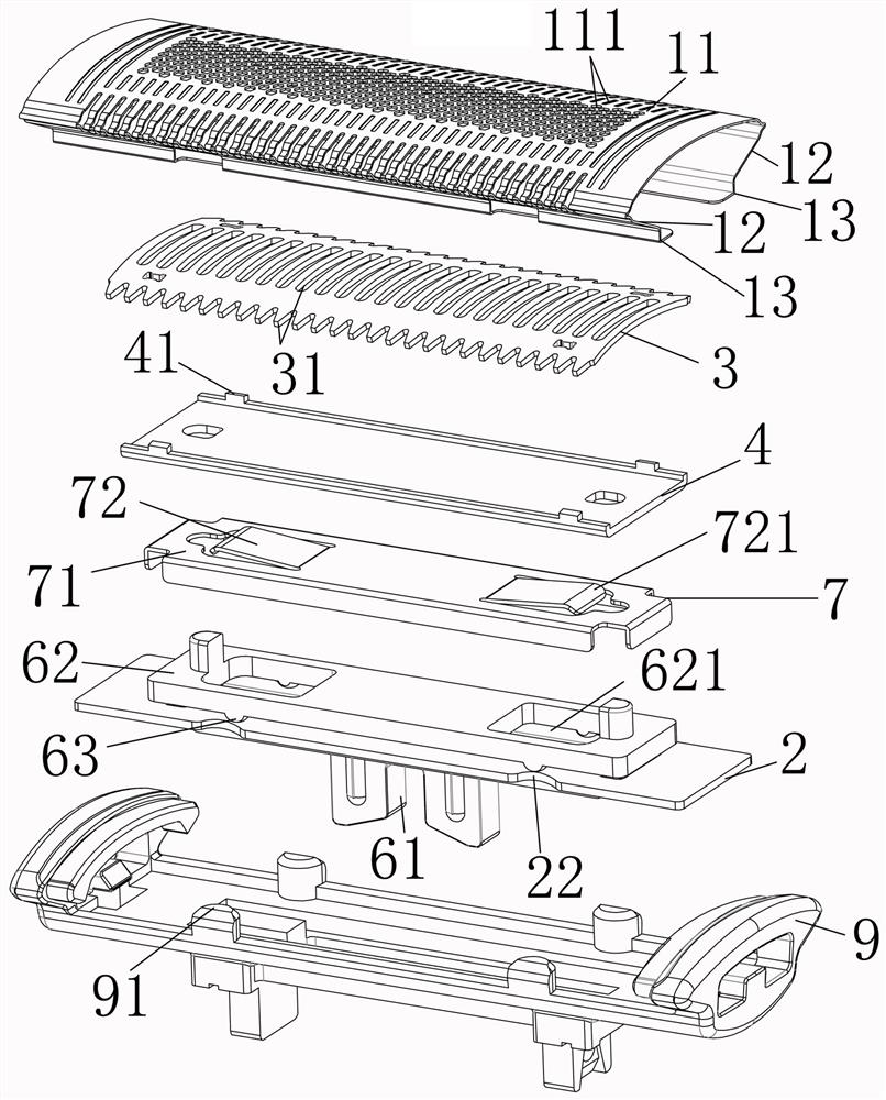
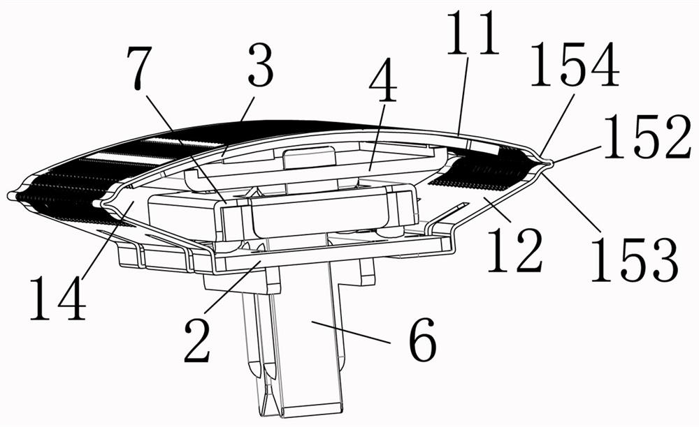
[0024] like figure 1 , figure 2 , image 3 , Figure 4 As shown, an embodiment of the reciprocating cutter head group of the present invention includes a housing 9, an arc-shaped fixed blade 1, a cutting movable knife 3 that is adapted to the fixed movable knife and has a cutting edge, and a The movable knife rest 4, the elastic body 7 arranged under the movable knife rest, the reciprocating transmission part 6, the holding plate 2 made of rigid material, the fixed blade 1 is as thin as 10 filaments or even as thin as 4-5 filaments The flexible metal sheet is integrally formed.

[0025] The fixed blade 1 includes a skin-friendly wall 11 that is used as a skin-facing wall and has a plurality of first hair inlets 111 during operation, two retracted walls 12 that respectively form retracted angles with both sides of the skin-friendly wall, and The two connecting parts 13 and the two retracting walls 12 are respectively connected with the arcs of the two retracting walls and ...


PUM


Abstract

A reciprocating type tool bit set comprises a shell, a fixed blade and a cutting movable blade which is matched with the fixed movable blade and provided with a cutting edge, and the fixed blade is integrally formed by a flexible metal sheet. The fixed blade comprises a skin-friendly wall which faces skin and is provided with a plurality of first hair inlets during operation, two inward-retracting walls which respectively form inward-retracting included angles with two sides of the skin-friendly wall, and two connecting parts which are respectively in arc connection with the two inward-retracting walls and are oppositely arranged, and the sections of the two inward-retracting walls and the connecting parts are L-shaped; the two inward-contracting walls and the two connecting parts are sequentially connected downwards from the two sides of the skin-friendly wall and are oppositely arranged, a containing groove with a cap-shaped section is formed, the containing groove is used for arranging a cutting movable knife, and a convex}-shaped or {-shaped mouth corner type connecting structure is formed between the skin-friendly wall and the inward-contracting walls. The mouth corner type connecting structure can well support the skin-friendly wall. And the thickness of the fixed blade is less than 10 filaments and even 4-5 filaments, so that the fixed blade is ultrathin which cannot be realized by other process structures.

Description

technical field [0001] The present invention relates to a reciprocating cutter head assembly, in particular to a reciprocating cutter head assembly for personal cleaning and care. Background technique [0002] At present, the reciprocating cutter heads on the market generally cannot shave the body hair of different lengths in one cut. Two sets of knives are needed. One set of knives cuts long hairs first, and the other set of knives shaves residual short hairs. Equipping with two cutter heads requires two cutting blades and a corresponding drive mechanism, which is not only heavy and easier to wear than standard single-purpose appliances, but also expensive to manufacture and assemble. At the same time, operating this combined device requires switching between different modes. , is more time-consuming, often complicated to operate, and the experience is quite uncomfortable. [0003] For the cutter head group itself, it generally includes a moving knife and an outer knife ne...

Claims


Application Information

Patent Timeline
Patent Type & Authority Applications(China)
IPC IPC(8): B26B19/04B26B19/38
CPCB26B19/04B26B19/3846B26B19/3813
Inventor 金炳杰
Owner 浙江精博五金科技有限公司
Why Eureka
Try Eureka