Mine vertical shaft composite shaft wall structure and construction method thereof

A vertical structure and shaft wall technology, applied in shaft equipment, mining equipment, earthwork drilling and mining, etc., can solve the problem of poor adhesion of outer shaft wall concrete, poor coordination of composite shaft wall structure, slow construction progress, etc. problems, to achieve the effect of simple construction, good stress effect, and enhanced pressure relief effect

Pending Publication Date: 2022-08-05
CINF ENG CO LTD
View PDF1 Cites 0 Cited by
  • Summary
  • Abstract
  • Description
  • Claims
  • Application Information

AI Technical Summary

Problems solved by technology

This kind of composite shaft wall structure with interlayer materials needs to be erected in stages to build the inner shaft wall and outer shaft wall concrete and lay the interlayer materials separately, resulting in slow construction progress
In addition, the interlayer materials used in the composite shaft wall structure often have poor adhesion to the inner shaft wall concrete and the outer shaft wall concrete, and the separated inner and outer shaft wall easy-to-leave layers and the composite shaft wall structure have poor overall coordination and stress effects

Method used


Image

  • Mine vertical shaft composite shaft wall structure and construction method thereof
  • Mine vertical shaft composite shaft wall structure and construction method thereof
  • Mine vertical shaft composite shaft wall structure and construction method thereof

Examples


Embodiment Construction

[0032] The present invention will be described in detail below with reference to the accompanying drawings and in conjunction with the embodiments. It should be noted that the embodiments of the present invention and the features of the embodiments may be combined with each other under the condition of no conflict. For the convenience of description, the words "up", "down", "left" and "right" appear in the following text, which only means that the directions of up, down, left and right are consistent with the drawings themselves, and do not limit the structure.

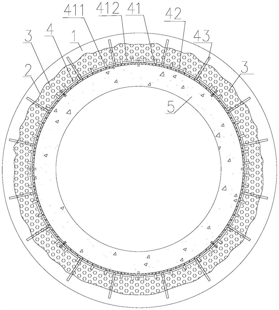
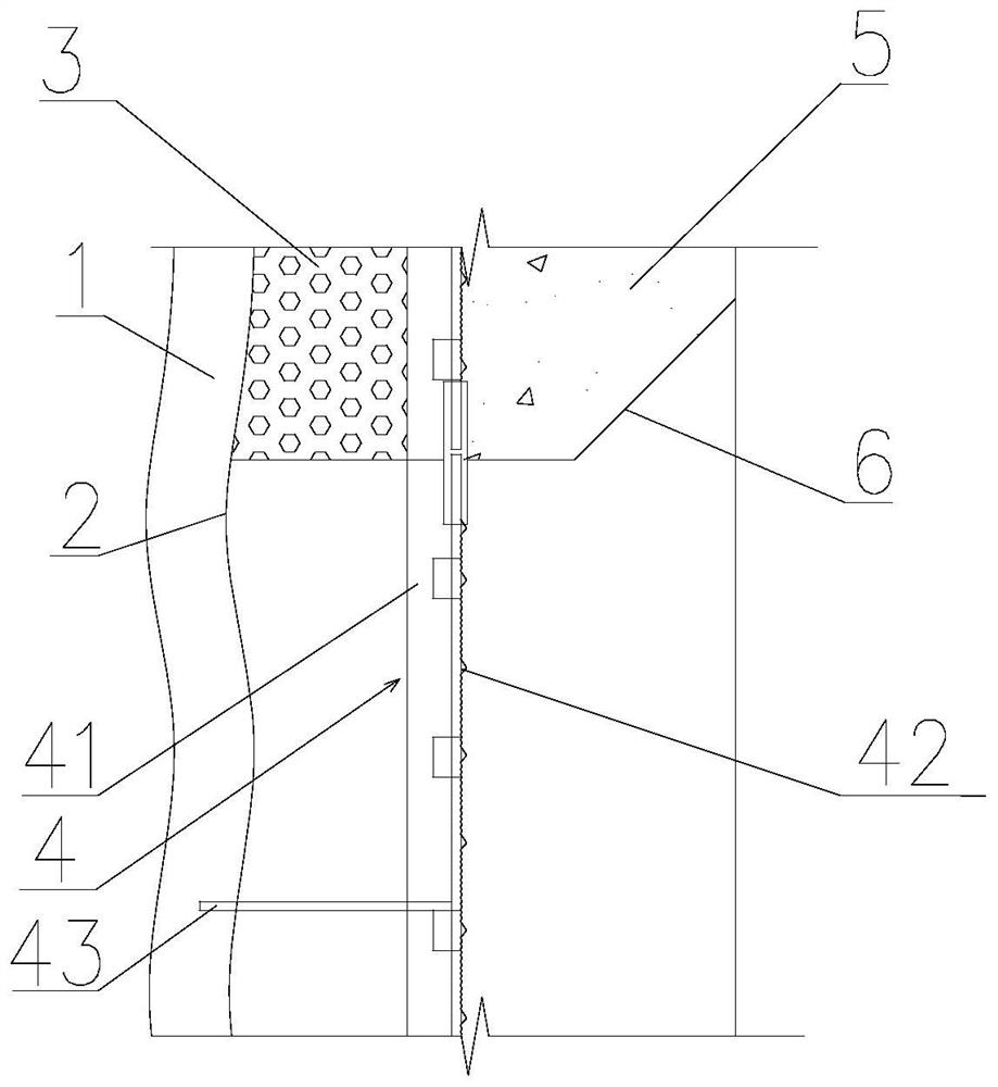
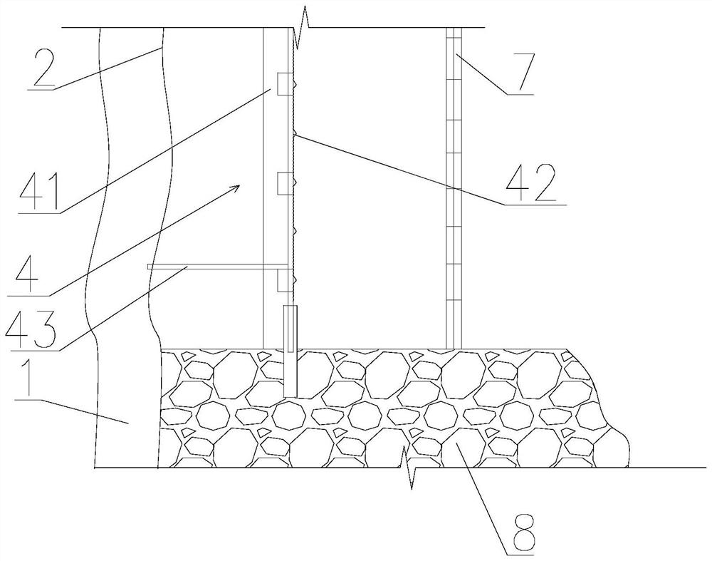
[0033] like figure 1 As shown, a composite shaft wall structure of a mine shaft includes an outer shaft wall 3 , an inner shaft wall 5 and a dismantling-free formwork layer 4 , and the dismantling-free formwork layer 4 includes a frame 41 and a formwork mesh 42 . The cross section of the frame 41 is a closed annular structure, one side of which is adjacent to the inner side surface of the outer shaft wall 3 , and the...


PUM


Abstract

The invention discloses a composite shaft wall structure of a mine shaft. The composite shaft wall comprises an outer-layer shaft wall, an inner-layer shaft wall and a non-dismantling formwork layer, and the non-dismantling formwork layer comprises a framework and a formwork net; the cross section of the framework is of a closed annular structure, one side of the framework is adjacent to the inner side face of the outer-layer well wall, and the template net is arranged on the other side of the framework. The formwork net is adjacent to the outer side face of the inner-layer well wall, and the framework and the formwork net can be formed by splicing blocks. The concrete strength grade of the outer-layer well wall is C1 to C10, and the thickness of the well wall is 100 to 300mm. The invention further discloses a construction method of the composite shaft wall structure of the mine shaft. The stress of the inner-layer well wall is reduced through the low elastic modulus and deformation yielding characteristics of the light porous structure of the outer-layer well wall, and the bonding effect between the outer-layer well wall and the inner-layer well wall is enhanced through the uneven and discontinuous structure of the template net, so that the overall coordination stress effect of the composite well wall structure is good, and the stability is high; during construction, the inner-layer well wall and the outer-layer well wall can be poured at the same time, construction is easy and fast, and safety is high.

Description

technical field [0001] The invention belongs to the technical field of mine shaft support, in particular to a mine shaft composite shaft wall structure and a construction method thereof. Background technique [0002] In recent years, mine shafts in my country have gradually entered the depth range of 1500-2500m. For example, the depth of the main shaft of the Shaling Gold Mine of Zhongjin Group exceeds 1600m, and the shafts under construction in the Xiling mining area of ​​Sanshandao Gold Mine exceed 2000m. The deep shaft faces the danger of strong rock burst caused by the deep high stress environment and the long-term large deformation of the weak and broken surrounding rock, which is easy to cause dynamic damage or progressive cumulative deformation damage of the shaft wall structure during the construction and service periods. [0003] China Utility Model Patent Authorization Announcement No. CN205743912U discloses a composite wellbore, which has a wellbore main body. The...

Claims


Application Information

Patent Timeline
Patent Type & Authority Applications(China)
IPC IPC(8): E21D5/04E21D5/06E21D5/11E21D5/12
CPCE21D5/04E21D5/06E21D5/11E21D5/12
Inventor 汪小东付宗智刘杰
Owner CINF ENG CO LTD
Why Eureka
Try Eureka