
Distributed optical fiber embedded plate spring preparation temperature visual monitoring method and device

A technology of distributed optical fiber and leaf spring, which is applied in measuring devices, thermometers with physical/chemical changes, thermometers, etc., can solve the problems of mold modification and high cost, and achieve the effect of an intuitive temperature monitoring method

Pending Publication Date: 2022-08-05
GUANGZHOU UNIVERSITY
View PDF0 Cites 0 Cited by
  • Summary
  • Abstract
  • Description
  • Claims
  • Application Information

AI Technical Summary

Problems solved by technology

The dielectric analyzer uses the change of the ionic conductivity of the resin itself during the curing reaction to change its dielectric properties. By monitoring the change of the dielectric properties during the curing process, the temperature change during the curing process can be inferred, but the The method needs to modify the mold, and the cost is relatively high

Method used


Image

  • Distributed optical fiber embedded plate spring preparation temperature visual monitoring method and device
  • Distributed optical fiber embedded plate spring preparation temperature visual monitoring method and device
  • Distributed optical fiber embedded plate spring preparation temperature visual monitoring method and device

Examples


Embodiment 1

[0060] According to an embodiment of the present invention, a visual monitoring device for the preparation temperature of a distributed optical fiber embedded leaf spring is provided, Figure 5 It is a schematic diagram of a distributed optical fiber embedded leaf spring preparation temperature visual monitoring device according to an embodiment of the present invention, such as Figure 5 As shown, according to the embodiment of the present invention, the distributed optical fiber-embedded plate spring preparation temperature visualization monitoring device specifically includes:

[0061] The temperature obtaining unit 50 obtains the temperature information of the leaf spring through a high-temperature-resistant single-mode optical fiber connected to the distributed optical fiber demodulator at one end, wherein the high-temperature-resistant single-mode optical fiber is laid on each layer of the glass fiber constituting the leaf spring according to a preset path between;

[0...

Embodiment 2

[0069] An electronic device according to an embodiment of the present invention includes:

[0070] processor; and,

[0071] A memory arranged to store computer-executable instructions which, when executed, cause the processor to perform the steps as described in the above-described method embodiments.

Embodiment 3

[0073]Embodiments of the present invention provide a storage medium for storing computer-executable instructions, where the computer-executable instructions, when executed, implement the steps described in the foregoing method embodiments.


PUM


Abstract

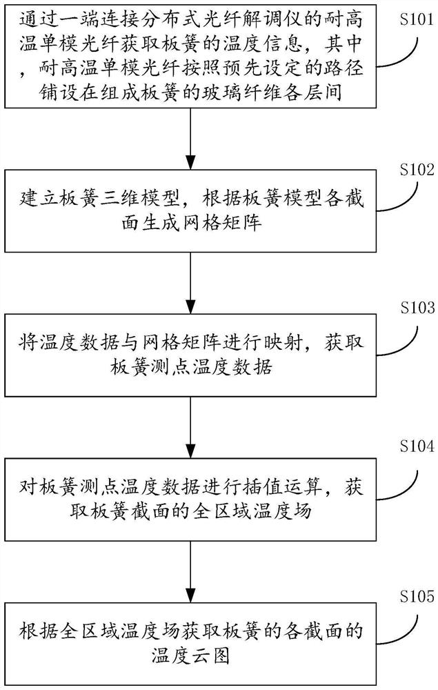
The embodiment of the invention provides a distributed optical fiber embedded plate spring preparation temperature visual monitoring method and device, and the method comprises the steps: obtaining the temperature information of a plate spring through a high-temperature-resistant single-mode optical fiber of which one end is connected with a distributed optical fiber demodulator, the high-temperature-resistant single-mode optical fibers are laid among layers of the glass fibers forming the plate spring according to a preset path; establishing a plate spring three-dimensional model, and generating a grid matrix according to each section of the plate spring model; mapping the temperature data and the grid matrix to obtain the temperature data of the leaf spring measuring point; interpolation operation is carried out on the plate spring measuring point temperature data, and a full-area temperature field of the section of the plate spring is obtained; and obtaining a temperature cloud picture of each section of the plate spring according to the full-region temperature field so as to solve the temperature monitoring problem of the composite material plate spring, and carrying out visualization processing on the full-region temperature field, so that a more convenient, comprehensive and visual temperature monitoring method can be provided.

Description

technical field [0001] This document relates to the technical field of distributed optical fiber sensing, and in particular, to a method and device for visual monitoring of temperature in the preparation of distributed optical fiber-embedded leaf springs. Background technique [0002] In recent years, with the development of advanced material science and composite material molding technology, fiber-reinforced composite materials are gradually replacing metal materials in some fields due to their high strength, light weight, fatigue resistance, easy automatic mass production, and easy modeling. , composite materials are known as the most promising materials in the 21st century. The leaf spring is an important part of the automobile suspension system, which plays the role of bearing pressure, shock absorption and buffering, and guiding during the driving process of the automobile. In the past, automobile leaf springs were generally made of alloy steel. The leaf springs made o...

Claims


Application Information

Patent Timeline
Patent Type & Authority Applications(China)
IPC IPC(8): G01K11/32
CPCG01K11/32
Inventor 朱萍玉林哲聪张帅麦建聪刘烁超
Owner GUANGZHOU UNIVERSITY
Learn More