Rotary disc type sensing element with unevenly distributed magnets
A technology of uniform distribution and sensing elements, which is applied to vehicle components, torque measurement, instruments, etc., can solve the problems of lack of power assistance, unstable operation of the motor, and the inability of permanent magnets to indicate the rotation position of the pedals, etc., to achieve structural Simple, low-cost effect
- Summary
- Abstract
- Description
- Claims
- Application Information
AI Technical Summary
Problems solved by technology
Method used
Image
Examples
Embodiment 1
[0060] Embodiment 1. Rotary disk sensor element with uneven distribution of multi-magnetic blocks
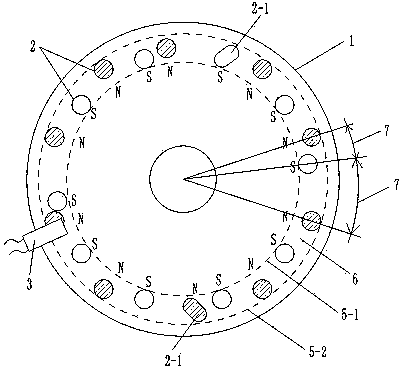
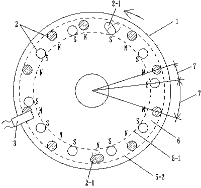
[0061] Such as figure 1 , 3 , 4, 5, 20 permanent magnet blocks 2 with a diameter of 0.8 cm are arranged on one surface of a high-strength plastic rotating disk 1 with a diameter of 10.0 cm, and the magnetic flux is 146---279 (B·H)max / KJ·m -3 one of the values in . The structure of rotating disk 1, permanent magnet block 2 and Hall 3 is as follows:
[0062] Each permanent magnet block 2 is fixed on the circular trajectory line 5-1 in the diameter of 8.5 centimeters, and within the circular ring 6 range between the outer circular trajectory line 5-2 of 9.5 centimeters, there are a plurality of permanent magnet blocks 2 into radius dislocations Distributed, there are a plurality of permanent magnet blocks 2 in dislocation distribution.
[0063] Radius dislocation distribution mode is: the plurality of permanent magnet blocks 2 are distributed within the scope of a circular r...
Embodiment 2
[0071] Embodiment 2. Rotary disk sensor element with uneven distribution of high-density magnetic blocks
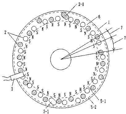
[0072] Such as figure 2 , 3, 4, 5, one surface of a high-strength aluminum rotating disk 1 with a diameter of 10.0 cm is provided with 40 permanent magnet blocks 2 with a diameter of 0.6 cm. The magnetic flux of the permanent magnet block 2 is 146---279 (B·H)max / KJ·m -3 A certain value, Hall 3 keeps a distance of 0.2 cm from each permanent magnet 2 in the rotating state, so that when each rotating permanent magnet 2 passes through Hall 3, Hall 3 can generate a corresponding Square wave electrical signal output. The structures of other rotating disk 1, permanent magnet block 2, and Hall 3 are the same as those in embodiment 1.
PUM
 Abstract
Description
Claims
Application Information
 - R&D
- Intellectual Property
- Life Sciences
- Materials
- Tech Scout
- Unparalleled Data Quality
- Higher Quality Content
- 60% Fewer Hallucinations
Browse by: Latest US Patents, China's latest patents, Technical Efficacy Thesaurus, Application Domain, Technology Topic, Popular Technical Reports.
© 2025 PatSnap. All rights reserved.Legal|Privacy policy|Modern Slavery Act Transparency Statement|Sitemap|About US| Contact US: help@patsnap.com


