Matching mounting device of CAN bus terminal resistor

A technology of CAN bus and terminal resistors, which is applied in the field of matching and mounting devices for CAN bus terminal resistors, can solve the problems of terminal resistor mismatch, affect normal communication, and cannot be handled flexibly, and achieve the effect of simple and convenient operation

Inactive Publication Date: 2022-08-05
ZHUZHOU JIACHENG TECH DEV CO LTD
View PDF0 Cites 2 Cited by
  • Summary
  • Abstract
  • Description
  • Claims
  • Application Information

AI Technical Summary

Problems solved by technology

[0003] like figure 1 As shown, the terminal resistance of the CAN bus is configured between CAN_H and CAN_L, which can generally only be realized by hardware welding, and the change can only be realized by dismantling. If multiple IO modules are involved in networking, the shell needs to be removed hard. And use an electric soldering iron to remove the redundant terminal resistance, which is prone to terminal resistance mismatch, and once the terminal resistance mismatch occurs, it will cause a large number of communication failures on the CAN bus, affecting its normal communication. In order to overcome this defect, the existing A device for automatically matching the terminal resistance of the CAN bus is disclosed in the technology. The optimal value of the resistance of the terminal resistance connected to the CAN bus is calculated through the cooperation of the control unit and the transceiver, and no welding and disassembly operations are required, saving time and effort, but This device mainly focuses on the selection of the terminal resistance value, and it cannot be flexibly handled when facing the terminal resistance matching and mounting problem when the CAN bus host and IO module are networked

Method used


Image

  • Matching mounting device of CAN bus terminal resistor
  • Matching mounting device of CAN bus terminal resistor
  • Matching mounting device of CAN bus terminal resistor

Examples


Embodiment 1

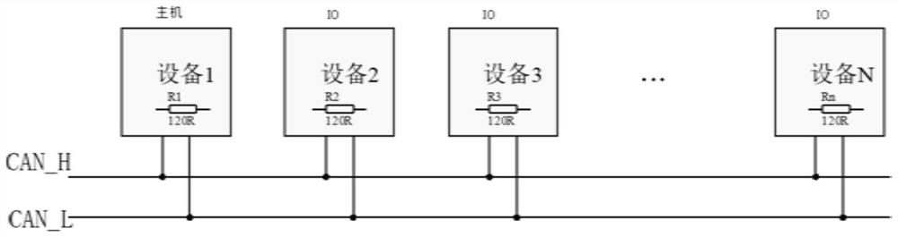
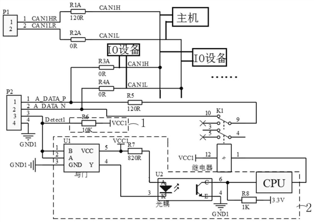
[0029] figure 2 In the CAN network shown, the box line represents the terminal resistance. Conventionally, when the terminal resistance is connected or disconnected, the method of welding or disassembly is generally used, which is very inflexible. The problem of matching and mounting the terminal resistance when the IO module is networked. This embodiment proposes a matching and mounting device for the terminal resistance of the CAN bus. image 3 shown, see image 3 , the device includes: a first external connector P1, a host connected to the CAN bus (for intuitive host access, see figure 1 ), several terminal resistors connected to the CAN bus, the second external connector P2, several IO devices connected to the CAN bus in turn from the host along the CAN bus (for the intuitive IO device access diagram, see figure 1 ), voltage source unit 1, central controller unit 2 and relays, see image 3, the terminal resistors connected to the CAN bus are R1A, R2A, R3A, R4A, R5, and...

Embodiment 2

[0039] based on image 3 The circuit structure diagram shown is described below from the networking of a single host and a single IO device. The host is the head end of the CAN network, using the first external connector P1, using external wiring selection, the first external connector P1 The first The pin and the second pin are short-circuited, the terminal resistance R1A and the terminal resistance R2A are connected between the high-order line CAN1_H of the CAN bus and the low-order line CAN1_L of the CAN bus, R1A is 120Ω, the terminal resistance R2A is 0Ω, and the host is mounted and connected to 120Ω Terminal resistance; when the first pin and the second pin are not short-circuited, the 120Ω terminal resistance will not be mounted and connected.

[0040] The IO device selects whether to hang the terminal resistor through the wiring plug with the pin of the second external connector P2 outside, short-circuit the fifth pin and the sixth pin of the second external connector P...

Embodiment 3

[0044] based on image 3 The shown circuit structure diagram is described below from the networking of a single host and multiple IO devices. The host is the head end of the CAN network, using the first external connector P1, using external wiring selection, the first external connector P1. The first pin and the second pin are short-circuited, the terminal resistance R1A and the terminal resistance R2A are connected between the high-order line CAN1_H of the CAN bus and the low-order line CAN1_L of the CAN bus, R1A is 120Ω, and the terminal resistance R2A is 0Ω. 120Ω terminal resistance; when the first pin and the second pin are not short-circuited, the 120Ω terminal resistance will not be mounted and connected.

[0045] The intermediate IO device selects whether to hang the terminal resistor through the wiring plug with the pin of the second external connector P2 outside. The central processing unit CPU collects the low level input from the fifth pin, and through its own sett...


PUM


Abstract

The invention provides a matching mounting device for a CAN bus terminal resistor, and relates to the technical field of CAN bus terminal resistor matching, a first pin and a second pin of a first external connector P1 are in short circuit, a terminal resistor is mounted between a high-position line and a low-position line of a CAN bus, a fifth pin and a sixth pin of a second external connector P2 are suspended, and the fifth pin and the sixth pin of the second external connector P2 are connected with the fifth pin and the sixth pin of the second external connector P1. The central controller unit automatically collects high level input of a fifth pin and outputs low level, a first end and a second end of a contact of a relay are not closed under the action of the low level, a terminal resistor is not connected to the CAN bus, the fifth pin and a sixth pin of a second external connector P2 are in short circuit, and the fifth pin and the sixth pin of the second external connector P2 are in short circuit. The central controller unit automatically collects low level input of the fifth pin and outputs high level, the first end and the second end of the contact of the relay are closed under the action of the high level, and the terminal resistor is connected to the CAN bus, so that quick matching and mounting of the terminal resistor are guaranteed, and operation is simple and convenient.

Description

technical field [0001] The invention relates to the technical field of CAN bus terminal resistance matching, and more particularly, to a matching and mounting device for CAN bus terminal resistance. Background technique [0002] CAN bus is one of the most widely used field buses in the world. The CAN bus network is mainly connected between CAN_H and CAN_L. The properties of CAN_H and CAN_L levels are different, and the two logic states of CAN_H level are high level states. and high-impedance state, the two logic states of CAN_L are low-level and high-impedance state, and the level of high-impedance state is uncertain. Therefore, in the differential transmission CAN bus, matching the terminal resistance can reduce the difference between CAN_H and CAN_H on the one hand. The function of the impedance in the CAN_L loop makes CANH and CANL have a certain level. On the other hand, the terminal resistance absorbs the reflection and echo of the signal to avoid the interference of th...

Claims


Application Information

Patent Timeline
Patent Type & Authority Applications(China)
IPC IPC(8): G05B19/042
CPCG05B19/0423G05B2219/21119Y02P90/02
Inventor 富弘毅杨来朱逸武
Owner ZHUZHOU JIACHENG TECH DEV CO LTD
Why Eureka
Try Eureka