Catheter reinforcing layer and catheter
A reinforcement layer and catheter technology, applied in the direction of the catheter, etc., can solve the problems of fracture failure mode, insufficient axial tensile performance of the catheter, etc., and achieve the effects of preventing fracture, optimizing transmission performance, and improving transmission efficiency
- Summary
- Abstract
- Description
- Claims
- Application Information
AI Technical Summary
Problems solved by technology
Method used
Image
Examples
Embodiment 1
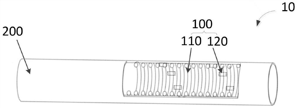
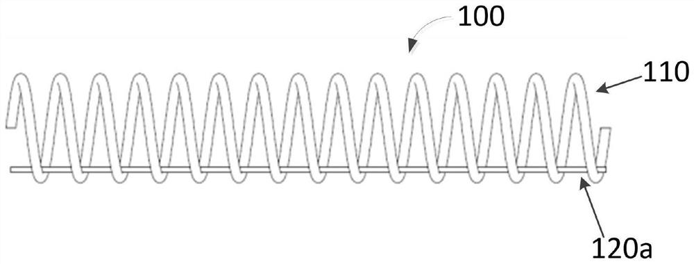
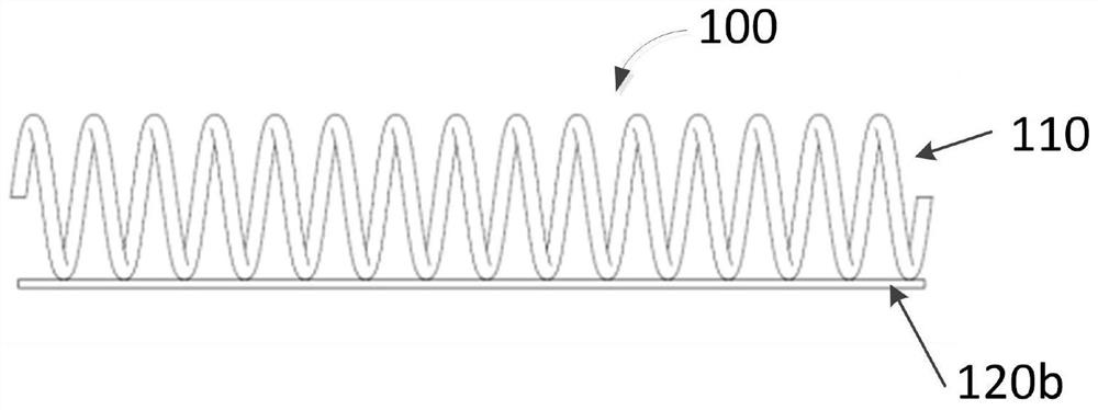
[0073] see Figures 2a-2c , Figures 2a-2c It is a schematic structural diagram of a conduit reinforcement layer according to an embodiment of the present invention, such as Figures 2a-2c shown, see also figure 1 , the catheter reinforcement layer 100 includes a spring member 110 and an axial member 120 extending from the proximal end to the distal end along the spring member 110 and passing through the spring member 110 as a whole. Specifically, as Figure 2a As shown, the axial member 120a may be attached between the spring member 110 and the inner layer (not shown) in a linear or helical shape from the proximal end to the distal end along the spring member 110 . or, as in Figure 2b As shown, the axial member 120b may be attached between the spring member 110 and the outer layer (not shown) in a linear or helical shape from the proximal end to the distal end. Or, as Figure 2c As shown, the axial members 120c may be staggered between the inner and outer surfaces of t...
Embodiment 2
[0075] see image 3 , image 3 It is a schematic structural diagram of a conduit reinforcement layer according to another embodiment of the present invention, such as image 3 As shown, the catheter reinforcement layer 100 is a combination of the spring member 110 and the axial member 120d, and the axial member 120d can be provided in the gap of the spring member 100 from the proximal end to the distal end along the spring member 100 between, and the axial member 120d and the spring member 110 are in the same plane. compared to Figures 2a-2c The conduit reinforcement layer 100 is shown, image 3 An advantage of the illustrated conduit reinforcement layer 110 is that the outer diameter dimension of the conduit comprising the conduit reinforcement layer is not increased by the presence of the axial member 120 .
[0076] It should be noted that, the axial member 120 provided by the present invention is combined with the spring member 110 as a conduit in a manner that the ent...
Embodiment 3
[0080] see Figure 4 , Figure 4 It is a schematic structural diagram of a conduit reinforcement layer according to another embodiment of the present invention, such as Figure 4 As shown, preferably, the catheter reinforcement layer 100 includes a spring member 110 and a plurality of axial members 120e which are symmetrically arranged throughout the spring member 110 from the proximal end to the distal end along the spring member 110 . Since the axial members 120e are disposed on the surface of the spring member 100 in a symmetrical manner, the structural stability of the catheter including the catheter reinforcement layer can be ensured. When the device is delivered in the body, the axial deformation of the catheter caused by the axial shear stress on the tube body of the catheter is avoided, that is, the axial tensile capacity of the catheter is improved, thereby reducing the elongation rate of the catheter, and finally avoiding the The risk of fatigue failure caused by a...
PUM
 Abstract
Description
Claims
Application Information
 - R&D
- Intellectual Property
- Life Sciences
- Materials
- Tech Scout
- Unparalleled Data Quality
- Higher Quality Content
- 60% Fewer Hallucinations
Browse by: Latest US Patents, China's latest patents, Technical Efficacy Thesaurus, Application Domain, Technology Topic, Popular Technical Reports.
© 2025 PatSnap. All rights reserved.Legal|Privacy policy|Modern Slavery Act Transparency Statement|Sitemap|About US| Contact US: help@patsnap.com


