Pipe supporting device for all-round laser cutting machine

A laser cutting machine and support device technology, applied in auxiliary devices, laser welding equipment, welding/cutting auxiliary equipment, etc., can solve problems such as inaccurate positioning of round pipes, improve processing quality, improve stability, and avoid shaking Effect

Pending Publication Date: 2022-08-09
JINAN G WEIKE SCI & TECH
View PDF0 Cites 0 Cited by
  • Summary
  • Abstract
  • Description
  • Claims
  • Application Information

AI Technical Summary

Problems solved by technology

[0004] The purpose of the present invention is to at least solve one of the technical problems existing in the prior art, and provide a pipe support device for an all-round laser cutting machine, which can solve the problem of clamping a round pipe by using a spring and an extruded plate. Hold, it will lead to the problem of inaccurate positioning of the round tube

Method used


Image

  • Pipe supporting device for all-round laser cutting machine
  • Pipe supporting device for all-round laser cutting machine
  • Pipe supporting device for all-round laser cutting machine

Examples


Embodiment 1

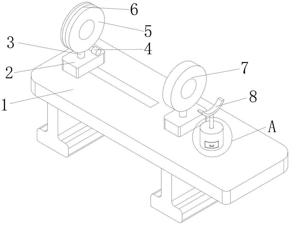
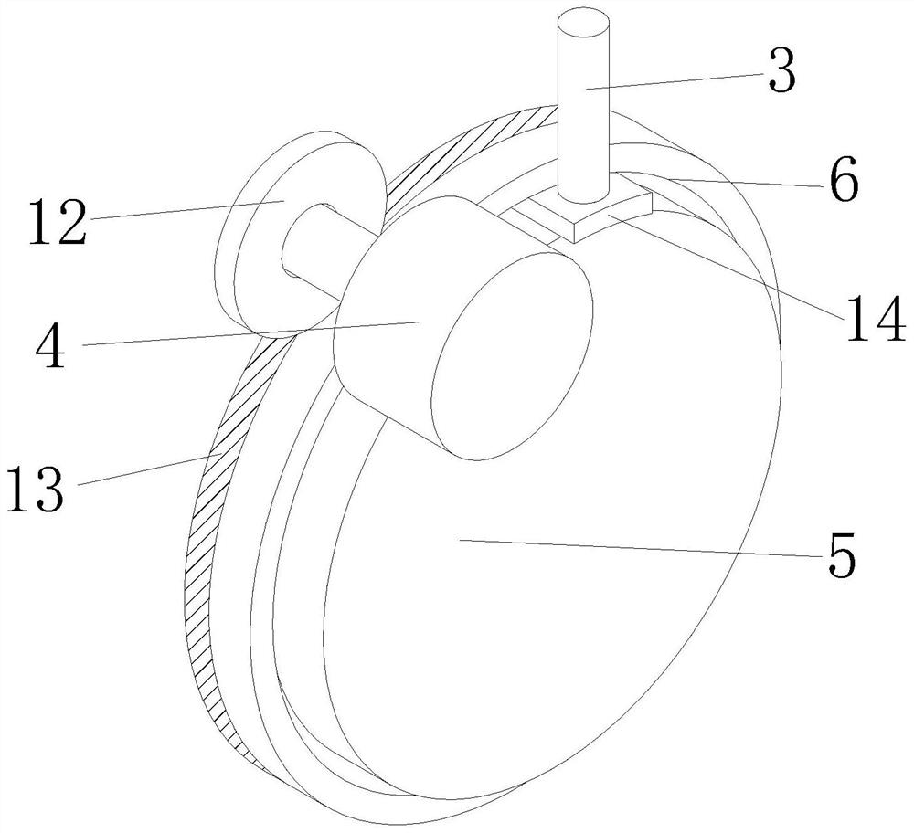
[0035] see Figure 1-8 , The present invention provides a technical solution: a pipe support device for an all-round laser cutting machine, comprising a support base 1, the surface of the support base 1 is slidably connected with a base 2, and the surface of the base 2 is fixedly connected with a connecting rod 3, The upper end of the connecting rod 3 is provided with a first fixing plate 5, the surface of the first fixing plate 5 is initially provided with a ring groove 6 with a convex cross-section, the inner wall of the ring groove 6 is slidably connected with the surface of the connecting rod 3, and the ring groove 6 is slidably connected. The inner wall is slidably connected with an arc-shaped first sliding block 14, and the surface of the first sliding block 14 is fixedly connected to the surface of the connecting rod 3, and then through the arc-shaped arrangement of the first sliding block 14, the first sliding block 14 and the ring The inner walls of the grooves 6 are ...

Embodiment 2

[0039] see Figure 1-8 , on the basis of the first embodiment, the surface of the first fixing plate 5 is provided with three chutes 20, and the cross-sections of the three chutes 20 are all elliptical, and a clamping mechanism is arranged inside the first fixing plate 5 to clamp The mechanism includes three second sliders 16 , the surfaces of the three second sliders 16 are respectively slidably connected with the inner walls of the three chutes 20 , and the shapes of the three second sliders 16 match the shapes of the three chutes 20 . , and then through the elliptical arrangement of the three second sliders 16 and the three chute 20, the frictional force when the second slider 16 slides in the chute 20 is reduced, the smoothness of the device is improved, and the The movement track of the second sliding block 16 is restricted, so that the second sliding block 16 can only slide smoothly in the chute 20 without shifting, thereby ensuring smooth operation.

[0040] The opposi...

Embodiment 3

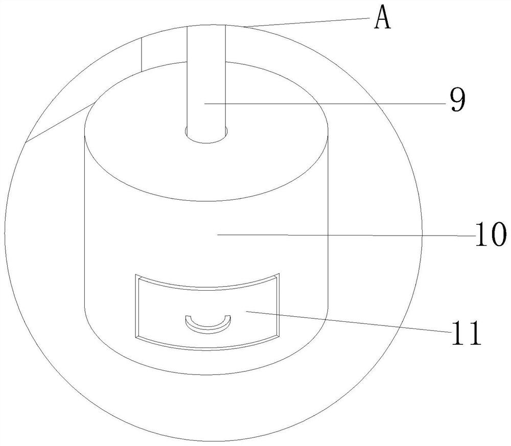
[0045] see Figure 1-8 , On the basis of Embodiment 1 and Embodiment 2, the surface of the support base 1 is fixedly connected with a collection cylinder 10, the interior of the collection cylinder 10 is slidably connected with a collection box 11, and the upper end of the collection cylinder 10 is slidably connected with a support cylinder 9, supporting The surface of the cylinder 9 is movably sleeved with a tension spring 25, and the two ends of the tension spring 25 are respectively fixedly connected to the inner wall of the collecting cylinder 10 and the surface of the supporting cylinder 9, and the upper end of the supporting cylinder 9 is fixedly connected with an arc-shaped support plate 8, It is used to support the circular pipe, and the arc-shaped support plate 8 enables the support plate 8 to fit more closely with the surface of the round pipe. At the same time, the tension spring 25 is set so that the height of the support plate 8 can be adjusted, and then The suppo...


PUM


Abstract

The invention discloses a pipe supporting device for an all-round laser cutting machine, and relates to the technical field of laser cutting, the pipe supporting device for the all-round laser cutting machine comprises a supporting base, the surface of the supporting base is slidably connected with a base, and the surface of the base is fixedly connected with a connecting rod; a first fixing disc is arranged at the upper end of the connecting rod, a clamping mechanism is arranged in the first fixing disc, and through the arrangement of the clamping mechanism, a worker only needs to rotate a worm, the circle center of a round pipe can coincide with the circle center of the first fixing disc, machining of the round pipe is facilitated, meanwhile, use of a spring is avoided as much as possible, and the machining efficiency is improved. The situation that when the round pipe is heavy, the spring is extruded, and consequently the round pipe is located inaccurately is avoided as much as possible, the machining quality of the round pipe is improved, meanwhile, meshing of the worm gear and the worm has self-locking performance, shaking generated in the round pipe machining process is avoided as much as possible, the influence on fixing of the round pipe is avoided as much as possible, and the fixing stability of the round pipe is improved.

Description

technical field [0001] The invention relates to the technical field of laser cutting, in particular to a pipe supporting device for an all-round laser cutting machine. Background technique [0002] As a fast and efficient processing method, laser cutting has been widely used in various industrial fields. Laser cutting machine is a kind of equipment for cutting and processing with laser beam, mainly including laser generator, beam expander, focusing mirror, working Table, plane fixture or rotating fixture and other related control units, in which the rotating fixture is used to clamp the pipe to be cut, the rotation of the fixture drives the pipe to rotate, and the laser cutting machine cuts the pipe. In order to avoid the pipe shaking during processing, it is necessary to use Fix the pipe to the pipe support device. [0003] However, when the existing pipe support device is in use, in order to be able to fix multi-sized pipes, especially round pipes, people often use arc-sh...

Claims


Application Information

Patent Timeline
Patent Type & Authority Applications(China)
IPC IPC(8): B23K26/70B23K26/38B23K37/053B23K101/06
CPCB23K26/702B23K26/38B23K37/053B23K2101/06
Inventor 蒋习锋王伟岳念举林如义
Owner JINAN G WEIKE SCI & TECH
Why Eureka
Try Eureka