Bicycle derailleur

A technology of speed changer and speed change plate, which is applied in the direction of bicycle gear shifting mechanism, bicycle accessories, transportation and packaging, etc., can solve the problems of high failure rate, complex structure, poor reliability and stability, etc.

Pending Publication Date: 2022-08-09
李树明
View PDF0 Cites 0 Cited by
  • Summary
  • Abstract
  • Description
  • Claims
  • Application Information

AI Technical Summary

Problems solved by technology

[0002] Most of the current bicycle transmissions use plastic hardware, which has high friction, small transmission force, low strength, high failure rate, low life, poor reliability and stability, inaccurate positioning, often out of gear, and complex structure.

Method used


Image

  • Bicycle derailleur
  • Bicycle derailleur
  • Bicycle derailleur

Examples


Embodiment approach

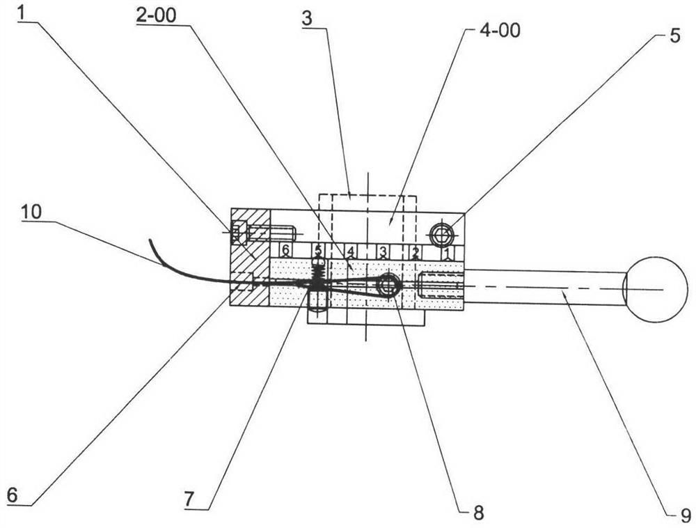
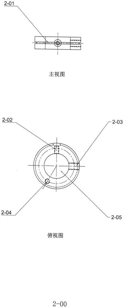
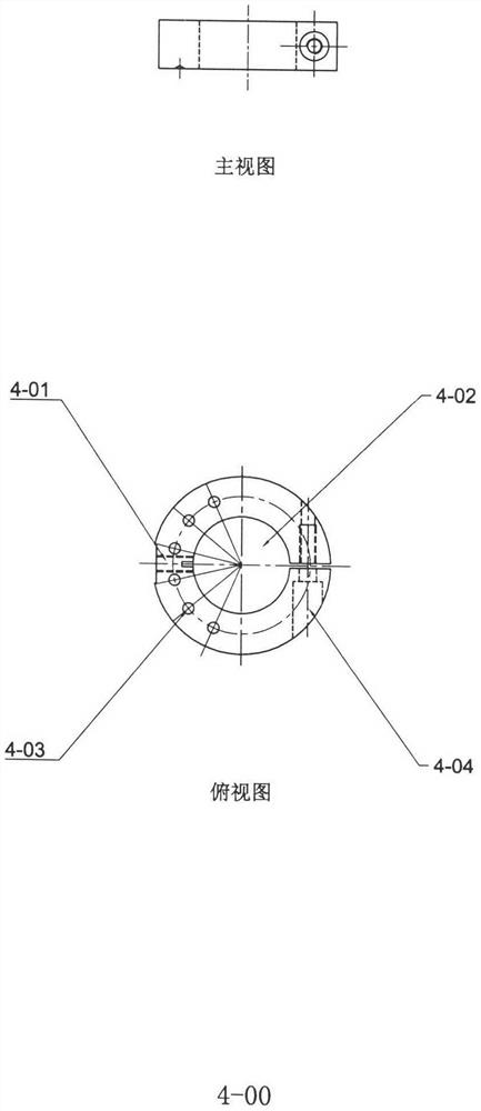
[0011] The transmission part is composed of: support plate (1), speed change plate (2-00), shaft sleeve (3), C-shaped fixing ring (4), positioning ball (7), handle (9), speed change line (10) ), the gear plate (2-00) is composed of: wire groove (2-01), wire fixing screw hole (2-02), handle hole (2-03), positioning bead hole (2- 04), the handlebar cover mounting hole (2-05) is composed of the C-shaped fixing ring (4-00) parts structure is: the support plate mounting hole (4-01), the handlebar cover mounting hole (2-02) , the positioning bead hole (2-03), the ring locking hole (4-04) is formed, the end of the C-shaped fixing ring (4-00) is drilled with 6 gear positioning socket holes or a few more, and The corresponding numbers 1-6 are engraved, and a locking screw (5) is also installed, which can be locked on any position of the shaft sleeve (3), and a support plate (1) with a threading hole (6) on it. ), fix the shifting cable (10) on the shifting disc (2-00) through the fixi...


PUM


Abstract

The invention relates to a bicycle transmission, in particular to a novel transmission of a metal structure, which is large in transmission force, high in strength, high in reliability, accurate in positioning, long in moving distance, multiple in gear, simple in structure, attractive in appearance and good in effect. The speed changer part is composed of a supporting plate (1), a speed changing disc (2-00), a shaft sleeve (3), a C-shaped fixing ring (4), a positioning ball (7), a handle (9) and a speed changing line (10), six gear positioning holes or more are drilled in the end face of the C-shaped fixing ring (4-00), corresponding numbers 1-6 are engraved, a locking screw (5) is further installed, the C-shaped fixing ring (4-00) can be locked at any position of the shaft sleeve (3), and the speed changing line (10) can be locked on the shaft sleeve (3). Positioning beads (7) are installed on the speed change disc and correspond to six gear positioning holes in the end face of a C-shaped fixing ring (4-00), a speed change cable (10) is fixed to the speed change disc (2-00), a handle (9) is toggled, and the speed change cable moves to drive a transmission piece.

Description

1. Technical field: [0001] The present invention relates to the invention of a bicycle transmission. 2. Background technology: [0002] Most of the current bicycle transmissions use plastic hardware, which has large friction, small transmission force, low strength, high failure rate, low life, poor reliability and stability, inaccurate positioning, frequent dislocation, and complex structure. 3. Contents of the Invention: [0003] In order to solve the above problems, the present invention adopts a transmission with a new metal structure, which has large transmission force, high strength, high reliability, accurate positioning, large moving distance, many gears, simple structure, beautiful appearance and good effect. [0004] Specific technical solutions: [0005] The transmission part is composed of: support plate (1), speed change plate (2-00), shaft sleeve (3), C-shaped fixing ring (4), positioning ball (7), handle (9), speed change line (10) ), the gear plate (2-00) ...

Claims


Application Information

Patent Timeline
IPC IPC(8): B62M25/04B62M25/02B62M25/00
CPCB62M25/04B62M25/02B62M25/00B62M2025/006B62M2025/003
Inventor 李树明
Owner 李树明
Why Eureka
Try Eureka