Smoke exhaust pipe, smoke exhaust system and gas water heater

A technology for gas water heaters and smoke exhaust pipes, which is applied to water heaters, fluid heaters, exhaust gas exhaust devices, etc., can solve the problems of shortening the service life of water heaters by smoke exhaust pipes, and achieve the purpose of avoiding unsmooth smoke exhaust, convenient manufacture, and extended The effect of service life

Pending Publication Date: 2022-08-09
GREE ELECTRIC APPLIANCES INC
View PDF0 Cites 0 Cited by
  • Summary
  • Abstract
  • Description
  • Claims
  • Application Information

AI Technical Summary

Problems solved by technology

[0004] Therefore, the technical problem to be solved by the present invention is to overcome the defect that the service life of the water heater is easily shortened due to the backflow of rainwater in the smoke exhaust pipe in the prior art, thereby providing a smoke exhaust pipe, a smoke exhaust system and a gas exhaust pipe that are not easy to cause rainwater backflow. water heater

Method used


Image

  • Smoke exhaust pipe, smoke exhaust system and gas water heater
  • Smoke exhaust pipe, smoke exhaust system and gas water heater
  • Smoke exhaust pipe, smoke exhaust system and gas water heater

Examples


Embodiment 1

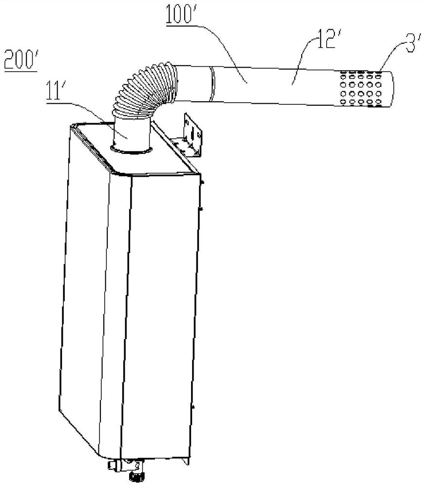
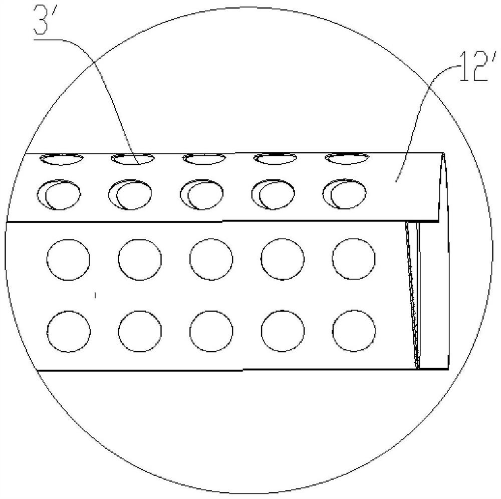
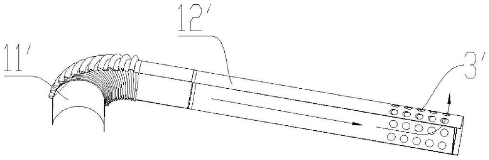
[0042] Figure 4 It is the gas water heater of Embodiment 3 of the present invention. Figure 5It is the exhaust pipe of the gas water heater according to the third embodiment of the present invention. like Figure 4 and Figure 5 As shown, the smoke exhaust pipe 100 in this embodiment mainly includes a pipe body and a smoke exhaust port 3 . The pipe body has a first section 11 suitable for connecting with the main body 201 of the gas water heater 200 and a second section 12 connecting with the first section 11 . The extending direction of the first segment 11 and the extending direction of the second segment 12 form an included angle. At least the inner tube wall of the second section 12 is recessed outward to form a groove 2 at the lower side thereof. For example, the second section 12 can be configured so that only the inner tube wall of the lower side is recessed outward to form a groove, or it can be configured that both the inner tube wall of the lower side and the ...

Embodiment 2

[0051] Embodiment 2 relates to a smoke exhaust system, which includes the above-mentioned smoke exhaust pipe 100, so it has the beneficial effect, that is, it can overcome the fact that the smoke exhaust pipe 100' in the prior art is prone to shorten the water heater due to the backflow of rainwater. defects in the service life.

Embodiment 3

[0053] Embodiment 3 relates to a gas water heater 200. The gas water heater 200 includes the above-mentioned smoke exhaust pipe 100, so it has the beneficial effect, that is, it can overcome the fact that the smoke exhaust pipe 100' in the prior art is easily shortened due to the backflow of rainwater. defects in the service life.


PUM


Abstract

The invention relates to a smoke exhaust pipe, a smoke exhaust system and a gas water heater. The smoke exhaust pipe comprises a pipe body and a smoke exhaust port. Wherein the pipe body is provided with a first section suitable for being connected with a main body of the gas water heater and a second section connected with the first section, an included angle is formed between the extending direction of the first section and the extending direction of the second section, and at least the inner pipe wall of the lower side of the second section is sunken outwards to form a groove; and the smoke outlet is formed on the groove wall of the groove. Even if an obtuse angle is formed between the second section of the pipe body and the first section of the pipe body due to installation errors or wind blowing and the like, rainwater entering the groove through the smoke exhaust port can flow to the lowest position of the groove under the action of gravity and then flow out through the smoke exhaust port in the groove. And the service life of the smoke exhaust pipe and the service life of the main body of the gas water heater cannot be shortened due to backflow into the main body of the gas water heater. Therefore, the smoke exhaust pipe can overcome the defect that the service life of the water heater is shortened due to the fact that a smoke exhaust pipe in the prior art easily causes rainwater backflow.

Description

technical field [0001] The invention relates to the technical field of water heaters, in particular to a smoke exhaust pipe, a smoke exhaust system and a gas water heater. Background technique [0002] A gas water heater, also known as a gas water heater, refers to a gas appliance that uses gas as a fuel and transfers heat to the cold water flowing through the heat exchanger through combustion heating to achieve the purpose of preparing hot water. The advantage is that it can be used right out of the box, without waiting, and with a small footprint. In terms of safety, the gas water heater realizes the separation of heat production and heat supply, bathing in the bathroom and installing it in the kitchen, avoiding the danger of leakage during the bathing process. [0003] like figure 1 and figure 2 As shown, the gas water heater 200' in the prior art generally discharges the flue gas generated by combustion out of the room through a smoke exhaust pipe 100'. 3', the pipe...

Claims


Application Information

Patent Timeline
Patent Type & Authority Applications(China)
IPC IPC(8): F23J11/02F23J13/08F23J13/00F24H1/10F24H9/20
CPCF23J11/02F23J13/08F23J13/00F24H1/10F24H9/20Y02B30/00
Inventor 李忠堂李凯张细燕
Owner GREE ELECTRIC APPLIANCES INC
Why Eureka
Try Eureka