Large-view-field image-space telecentric conoscopic optical system for industrial chromaticity and brightness detection

A brightness detection and optical system technology, applied in the field of optical systems, can solve the problems that industrial lenses cannot meet the brightness and chromaticity of multiple angles, the brightness measurement results have a great influence, and the uniformity of chromaticity and chromaticity is affected.

Pending Publication Date: 2022-08-09
SUZHOU UNIV
View PDF0 Cites 1 Cited by
  • Summary
  • Abstract
  • Description
  • Claims
  • Application Information

AI Technical Summary

Problems solved by technology

For conventional flat panel display devices on the market, the brightness and chromaticity detection method is mainly through point vertical measurement or area array measurement, but this method can only measure the luminance of a specific angle, and the actual display device has different luminous angles. When the measurement angle changes, it will have a great impact on the luminance measurement results, thereby affecting the chromaticity and chromaticity uniformity. Traditional industrial lenses cannot meet the measurement of luminance and chromaticity at multiple angles.

Method used


Image

  • Large-view-field image-space telecentric conoscopic optical system for industrial chromaticity and brightness detection
  • Large-view-field image-space telecentric conoscopic optical system for industrial chromaticity and brightness detection
  • Large-view-field image-space telecentric conoscopic optical system for industrial chromaticity and brightness detection

Examples


Embodiment 1

[0055] Below in conjunction with accompanying drawing and embodiment, the present invention is further described:

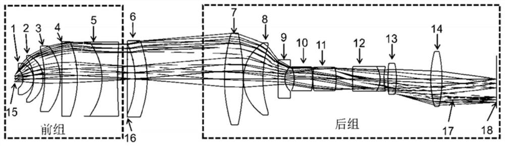
[0056] A telecentric conoscopic optical system with a large field of view for industrial chromaticity and brightness detection, such as figure 1 Shown: it consists of a front lens group and a rear lens group, a sixth spherical lens 6 is arranged between the front lens group and the rear lens group, and the front lens group includes a first spherical lens 1 and a second spherical lens 2. The third spherical lens 3, the fourth spherical lens 4 and the fifth cemented spherical lens 5; the primary image surface 16 of the front lens group is arranged between the fifth cemented spherical lens and the sixth spherical lens; the rear lens group includes Seventh Spherical Lens 7, Eighth Spherical Lens 8, Ninth Spherical Lens 9, Tenth Spherical Lens 10, Eleventh Spherical Lens 11, Twelfth Cemented Spherical Lens 12, Thirteenth Spherical Lens 13, Fourteenth Spherical Lens T...

Embodiment 2

[0070] The entrance pupil diameter of the lens is D=3.6mm, and the field of view is 130°. The focus is adjusted by moving the relative distance between the front group and the rear group. The focus range is 250mm~∞. The design parameters of the optical system are shown in Table 3, and the focusing distances of the front and rear groups with different object distances are shown in Table 4. The MTF curves of different object distances under the full field of view are shown in Figure 7(a), Figure 7(b), and Figure 7, respectively. (c), as shown in Figure 7(d), the MTF values ​​are all 100lp / mm≥0.3, with high resolution; the distortion is as follows Figure 8 As shown, its value is less than 43%, which is within the acceptable range; the telecentricity of this conoscope lens is as follows Figure 9 As shown, its telecentricity CRA≤0.05.

[0071] Table 3. Design parameters of the 130° conoscopic optical system in the field of view

[0072]

[0073]

[0074] Table 4. The focu...

Embodiment 3

[0077] The entrance pupil diameter of the lens is D=3.6mm, and the field of view is 140°. The focus is adjusted by moving the relative distance between the front group and the rear group. The focus range is 250mm~∞. The design parameters of the optical system are shown in Table 5, and the focusing distances of the front and rear groups with different object distances are shown in Table 6. The MTF curves of different object distances under the full field of view are shown in Figure 10(a), Figure 10(b), and Figure 10, respectively. (c), as shown in Figure 10(d), the MTF values ​​are all 100lp / mm≥0.15, with high resolution; the distortion is as follows Figure 11 As shown, its value is less than 50%, which is within the acceptable range; the telecentricity of this conoscope lens is as follows Figure 12 As shown, its telecentricity CRA≤0.05.

[0078] Table 5. Design parameters of the 140° conoscopic optical system in the field of view

[0079]

[0080]

[0081] Table 6. F...


PUM


Abstract

The invention discloses a large-field-of-view image space telecentric conoscopic optical system for industrial chromaticity and brightness detection, and the system consists of a front lens group and a rear lens group, and a sixth spherical lens is disposed between the front lens group and the rear lens group. The front group of lenses comprises a first spherical lens, a second spherical lens, a third spherical lens, a fourth spherical lens and a fifth glued spherical lens; and the rear group of lenses comprises a seventh spherical lens, an eighth spherical lens, a ninth spherical lens, a tenth spherical lens, an eleventh spherical lens, a twelfth cemented spherical lens, a thirteenth spherical lens, a fourteenth spherical lens and an image surface. The device and the method have the beneficial effects that visual angle performance measurement data of a display can be quickly and accurately acquired in real time, the chromaticity, brightness and contrast of multi-angle light source distribution under a large visual angle are measured, visual angle data of a complete cone is acquired through single measurement, an accurate measurement result is quickly provided, and the measurement accuracy is improved. And the system can become a choice for various research and development projects and online production quality control applications.

Description

technical field [0001] The invention relates to the technical field of optical systems, in particular to a conoscopic optical system with a large field of view and a telecentric image side for industrial chromaticity and brightness detection. Background technique [0002] With the development of science and technology, the industrial revolution is no longer at the level of simple industrialization. Machine vision can replace the traditional manual detection method, greatly improving the efficiency and effect of industrial manufacturing, thereby greatly improving the quality of products in the market. , as an important part of machine vision, industrial lens directly affects the overall performance of the system. For the conventional flat panel display device brightness and chromaticity detection methods on the market, it is mainly through point vertical measurement or area array measurement, but this method can only measure the luminous brightness of a specific angle, and th...

Claims


Application Information

Patent Timeline
Patent Type & Authority Applications(China)
IPC IPC(8): G02B13/00G02B13/22
CPCG02B13/0045G02B13/005G02B13/006G02B13/22
Inventor 许峰王霖
Owner SUZHOU UNIV
Why Eureka
Try Eureka