Lattice type large antenna azimuth seat frame with tower footing

An antenna azimuth and grid structure technology, applied in antennas, antenna parts, antenna supports/mounting devices, etc., can solve the problem of reducing antenna anti-wind load disturbance and anti-overturning moment, unable to meet the needs of large reflector antennas, Reduce the ability of the seat frame to withstand horizontal loads, etc., to achieve the effect of improving the anti-overturning ability, avoiding contact stress differences, and improving the bearing capacity

Pending Publication Date: 2022-08-09
NO 54 INST OF CHINA ELECTRONICS SCI & TECH GRP
View PDF3 Cites 0 Cited by
  • Summary
  • Abstract
  • Description
  • Claims
  • Application Information

AI Technical Summary

Problems solved by technology

[0004] (1) The rigidity of the frame with a single steel box girder structure is relatively weak. To increase the rigidity of the frame, it is necessary to increase the section size of the box girder, which will increase the weight very quickly, especially for large and super large antennas. Exponentially increasing; since the cross-sectional dimensions of steel box girders are usually very large, there is a risk of local instability of the connection between the girders
[0005] (2) In the traditional azimuth seat frame structure, the central pivot is usually located on the bottom surface of the seat frame, and the horizontal load of the seat frame needs to be transmitted to the pivot position through long-distance transmission of oblique supports, which will increase the structure of the seat frame Deformation affects the performance of the antenna; when the central pivot is on the bottom of the mount, the antenna's anti-wind load disturbance and anti-overturning moment are reduced, which reduces the dynamic performance of the antenna
[0006] (3) The receiving or transmitting equipment of a large antenna is generally located in the center body on the back of the antenna, which is very high from the ground, which will bring great inconvenience to operation and maintenance
[0008] (1) The antenna pedestal involved in the first patent is in the form of a box girder structure, which is heavy; the central pivot is located at the bottom of the pedestal, and the force transmission path is long, which reduces the ability of the pedestal to withstand horizontal loads; Contains only two rollers, when the antenna diameter increases and the weight of the antenna increases, the bearing capacity of a single wheel is limited
[0009] (2) The antenna pedestal involved in the second patent is a column structure. The azimuth rotation part of this type of pedestal adopts rolling bearings. Due to the limitation of processing and manufacturing, the diameter of the bearing can only reach the meter level, which cannot meet the requirements of large-scale Requirements for reflector antennas
[0010] (3) The antenna pedestal involved in the third patent is in the form of a parallel mechanism. Although this type of pedestal can meet the overhead tracking requirements of the antenna, the antenna will generate spin during the motion process. In the non-circular polarization working mode , there will be a large polarization loss
In addition, this type of mount is not suitable for large antennas, especially when the caliber reaches the 100-meter level

Method used


Image

  • Lattice type large antenna azimuth seat frame with tower footing
  • Lattice type large antenna azimuth seat frame with tower footing
  • Lattice type large antenna azimuth seat frame with tower footing

Examples


Embodiment Construction

[0047] The present invention will be further described below with reference to the accompanying drawings and specific embodiments.

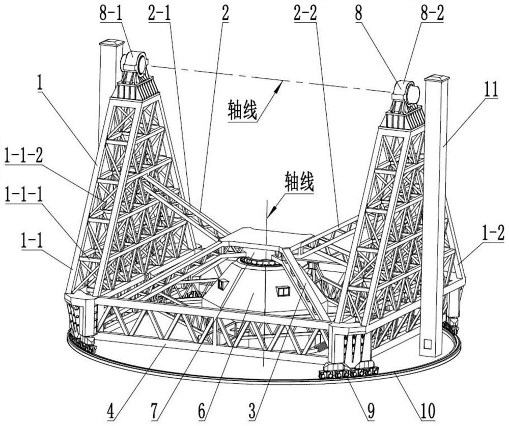
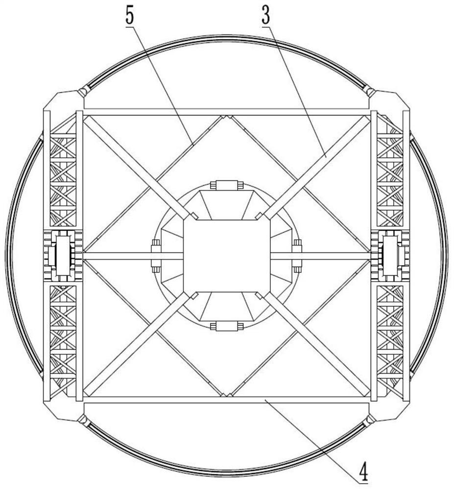
[0048] The embodiment of the present invention uses a reflector antenna with an aperture greater than 50 meters as an example, such as figure 1 As shown, the azimuth seat frame of the present invention includes: a main support truss 1, a side support beam 2, a radial inclined beam 3, a lower side beam 4, an inner inclined beam 5, a center tower base 6, a center pivot 7, a bearing seat 8, Roller mechanism 9 and track 10.

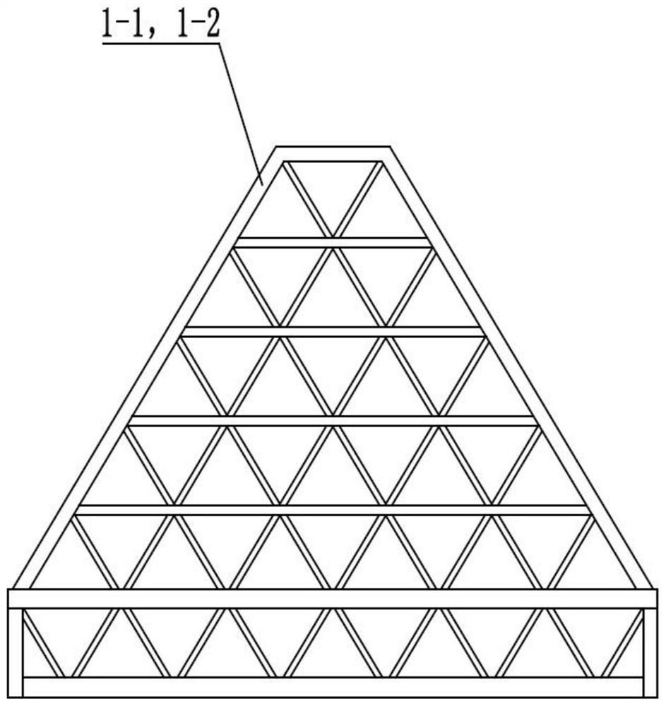
[0049] like Figures 1 to 3 As shown in the figure, the main support truss 1 is composed of a left main support truss 1-1 and a right main support truss 1-2, which are arranged symmetrically on the left and right. The outlines of the left main support truss 1-1 and the right main support truss 1-2 are The triangular and double-layer lattice structure is composed of several regular triangular meshes, and there are multiple beam...


PUM


Abstract

The invention discloses a lattice type large antenna azimuth seat frame with a tower footing, and relates to an antenna technology in the fields of communication, measurement and control, radar, radio astronomy and the like. The invention discloses a seat frame, and aims to provide a seat frame which is high in rigidity, strong in overturning resistance, large in equipment operation space and not easy to destabilize. The device comprises a main supporting truss, a side supporting beam, a radial oblique beam, a lower edge beam, an inner oblique beam, a central tower footing, a central pivot, a bearing seat, a roller mechanism and a track. The main supporting truss is of a lattice structure and is composed of a plurality of triangular grids. The central tower footing is located in the center of the seat frame, the upper portion of the central tower footing is a central pivot, and the side supporting beams and the radial oblique beams intersect on the central pivot. The rolling wheel mechanism is composed of four sets, each set of rolling wheel mechanism comprises eight rolling wheels, and the rolling wheels are arranged in a one-to-two mode, a two-to-four mode and an eight-to-four mode. According to the invention, the overall rigidity and wind load resistance of the seat frame structure are effectively improved, and the seat frame structure is particularly suitable for design and manufacturing of azimuth seat frames of large and ultra-large antennas.

Description

technical field [0001] The invention relates to antenna technology in the fields of communication, measurement and control, radar and radio astronomy, and more particularly, to a lattice type large-scale antenna azimuth mount with a tower base. Background technique [0002] Reflector antennas are widely used in the fields of communication, measurement and control and radio astronomy because of their strong directivity. In particular, large-diameter antennas play an important role in deep space communication and astronomical observations because of their high gain and high resolution. Large-scale reflector antennas generally take the form of azimuth-elevation mounts to cover the entire airspace. The azimuth mount is usually located at the bottom of the antenna, and its function is to support the weight of the pitch part and complete the rotation function. Therefore, it is the core component of the reflector antenna system. [0003] The azimuth mount of the large reflector an...

Claims


Application Information

Patent Timeline
Patent Type & Authority Applications(China)
IPC IPC(8): H01Q1/12H01Q1/00H01Q15/14H01Q19/10
CPCH01Q1/1242H01Q1/005H01Q15/14H01Q19/10
Inventor 郑元鹏刘国玺伍洋张亚林郝会乾卢兴明王宇哲陈隆
Owner NO 54 INST OF CHINA ELECTRONICS SCI & TECH GRP
Why Eureka
Try Eureka