
Portable electronic equipment and electronic equipment system

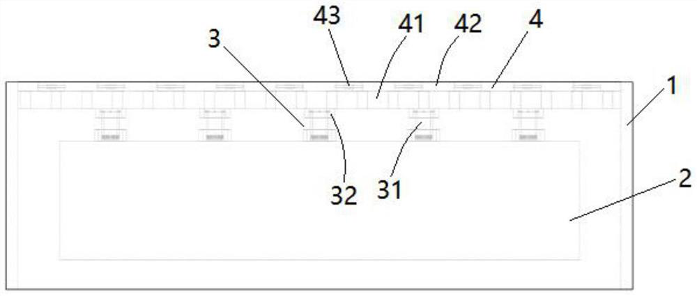
A kind of electronic equipment and portable technology, which is applied in the direction of cooling/ventilation/heating transformation, instruments, casings/cabinets/drawer parts, etc., which can solve problems such as noise generation, shortened service life, and poor release of equipment performance. Achieve the effect of avoiding damage and improving heat dissipation efficiency

Pending Publication Date: 2022-08-09
扬州可为电子有限公司
View PDF0 Cites 0 Cited by
  • Summary
  • Abstract
  • Description
  • Claims
  • Application Information

AI Technical Summary

Problems solved by technology

[0002] Portable electronic devices are widely favored because they are easy to carry and can be used in various places. As we all know, the integrated circuits inside portable electronic devices will generate high temperature accumulation under long-term work, which will lead to unstable operation of the system. , so that the service life is shortened, and even some components are burned, resulting in high temperature heat not from the outside but from the inside. Inside the server, the processor (CPU) and the graphics card (GPU) are the main parts of the heat. When the temperature is too high, it will directly affect its processing performance. Therefore, it is necessary to use a radiator module to dissipate heat to ensure that the temperature of the internal components is normal. However, the water-cooled radiator used in the prior art has a large safety hazard when dissipating heat. When the fan dissipates heat, it will generate noise. Under long-term use, due to untimely heat dissipation, the performance release of the device will deteriorate, which will affect the usability of the device. At the same time, the noise will cause harm to the internal electronic components and damage the service life of the portable device.

Method used


Image

  • Portable electronic equipment and electronic equipment system

Examples


Embodiment Construction

[0025] The present invention will be described in detail below with reference to the various embodiments shown in the accompanying drawings, but it should be noted that these embodiments do not limit the present invention. Equivalent transformations or substitutions all fall within the protection scope of the present invention.

[0026] It should be noted that the embodiments in the present application and the features of the embodiments may be combined with each other in the case of no conflict. In the description of this application, it should be noted that, unless otherwise expressly specified and limited, the terms "installed", "connected" and "connected" should be understood in a broad sense, for example, it may be a fixed connection or a detachable connection Connection, or integral connection; it can be mechanical connection or electrical connection; it can be directly connected or indirectly connected through an intermediate medium, and it can be internal communication...


PUM


Abstract

The invention provides portable electronic equipment. The portable electronic equipment comprises a shell, a plurality of electronic devices, a heat dissipation device and a noise reduction device, wherein the electronic devices are contained in a cavity formed in the shell and used for achieving the portable electronic equipment, and the heat dissipation device and the noise reduction device are arranged in the shell and used for monitoring the working states of the electronic devices in a matched mode and conducting drive control heat dissipation. The heat dissipation device comprises a temperature sensor, heat dissipation units arranged on a heat source and a driving unit for driving heat dissipation by receiving signal transmission of the temperature sensor, and the noise reduction device comprises a sound sensor and a noise reduction assembly for responding to a noise threshold value and performing noise reduction processing; the sound absorption interlayer and the sound attenuation interlayer are arranged towards the sound source, the sound direction adjusting piece and the sound processing unit are arranged in the sound attenuation interlayer, the sound absorption interlayer is in a honeycomb shape and is filled with sound absorption materials, and a plurality of sound absorption grooves are formed in the sound attenuation interlayer. The portable electronic equipment disclosed by the invention has the performance of active noise reduction and heat dissipation.

Description

technical field [0001] The present invention relates to the technical field of electronic devices, and more particularly to a portable electronic device and an electronic device system. Background technique [0002] Portable electronic devices are widely favored because they are easy to carry and can be used in various places. It is well known that integrated circuits inside portable electronic devices will generate high temperature accumulation under long-term work, resulting in unstable system operation. , which shortens the service life and even causes some parts to burn out. The heat that causes high temperature does not come from the outside but from the inside. Inside the server, the processor (CPU) and the graphics card (GPU) are the main parts of heat. When the temperature is too high, it will directly affect its processing performance, so it is necessary to use a radiator module to dissipate heat to ensure that the temperature of the internal components is normal. ...

Claims


Application Information

Patent Timeline
Patent Type & Authority Applications(China)
IPC IPC(8): H05K7/20H05K5/02G10K11/172G10K11/162G10K11/16
CPCH05K7/20136H05K7/20209H05K5/0086H05K5/0217G10K11/16G10K11/162G10K11/172
Inventor 丁爱军
Owner 扬州可为电子有限公司
Learn More