Cooling device for water-cooled IC engine

A technology of cooling device and internal combustion engine, which is applied in the direction of engine cooling, liquid cooling, mechanical equipment, etc. It can solve the problem of cooling device cooling capacity drop, achieve the effect of reducing flow resistance, reducing cost and improving vibration resistance

Inactive Publication Date: 2004-05-12
HONDA MOTOR CO LTD
View PDF0 Cites 0 Cited by
  • Summary
  • Abstract
  • Description
  • Claims
  • Application Information

AI Technical Summary

Problems solved by technology

[0004] In the cooling device described in the Publication No. 59-134777, if the cooling device is miniaturized and the heat dissipation load per unit surface area of ​​the heat sink is increased, then in the normal driving state, the air blown from front to rear The driving wind flows along the upper and lower sides of the flat heat sink, and the cooling water in the cooling water pipe connected to the flat heat sink is fully cooled by using the two sides of the flat heat sink. However, if it is summer, if it is When encountering traffic jams, repeated low-speed driving, and parking, the external air between the upper and lower flat heat sinks stays in a state of being heated to a high temperature in the space between the above heat sinks, and the external air and cooling water pipes The heat exchange between the cooling water in the cooling water cannot be carried out smoothly, and the cooling capacity of the cooling device is greatly reduced

Method used


Image

  • Cooling device for water-cooled IC engine
  • Cooling device for water-cooled IC engine
  • Cooling device for water-cooled IC engine

Examples


Embodiment Construction

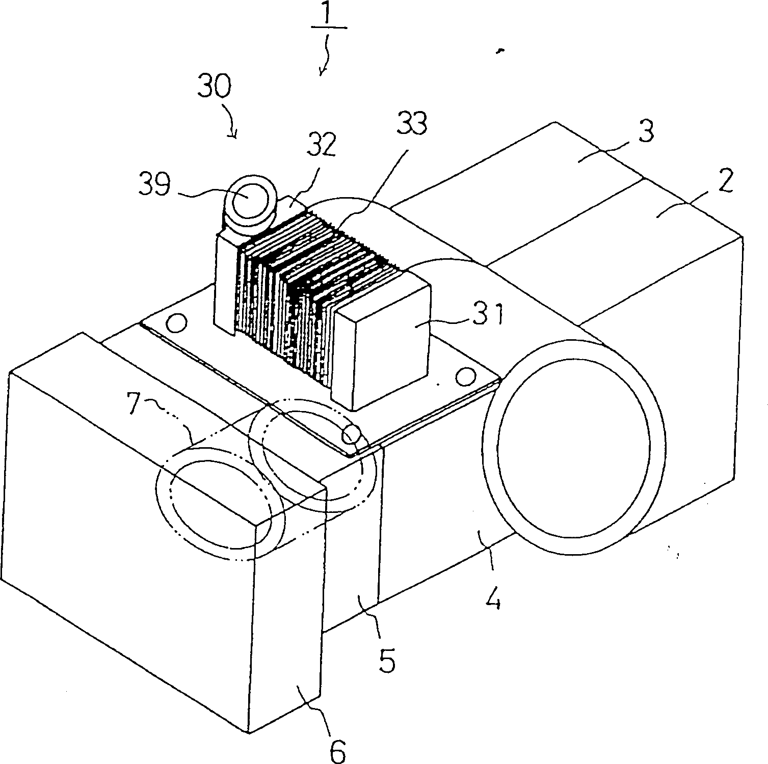
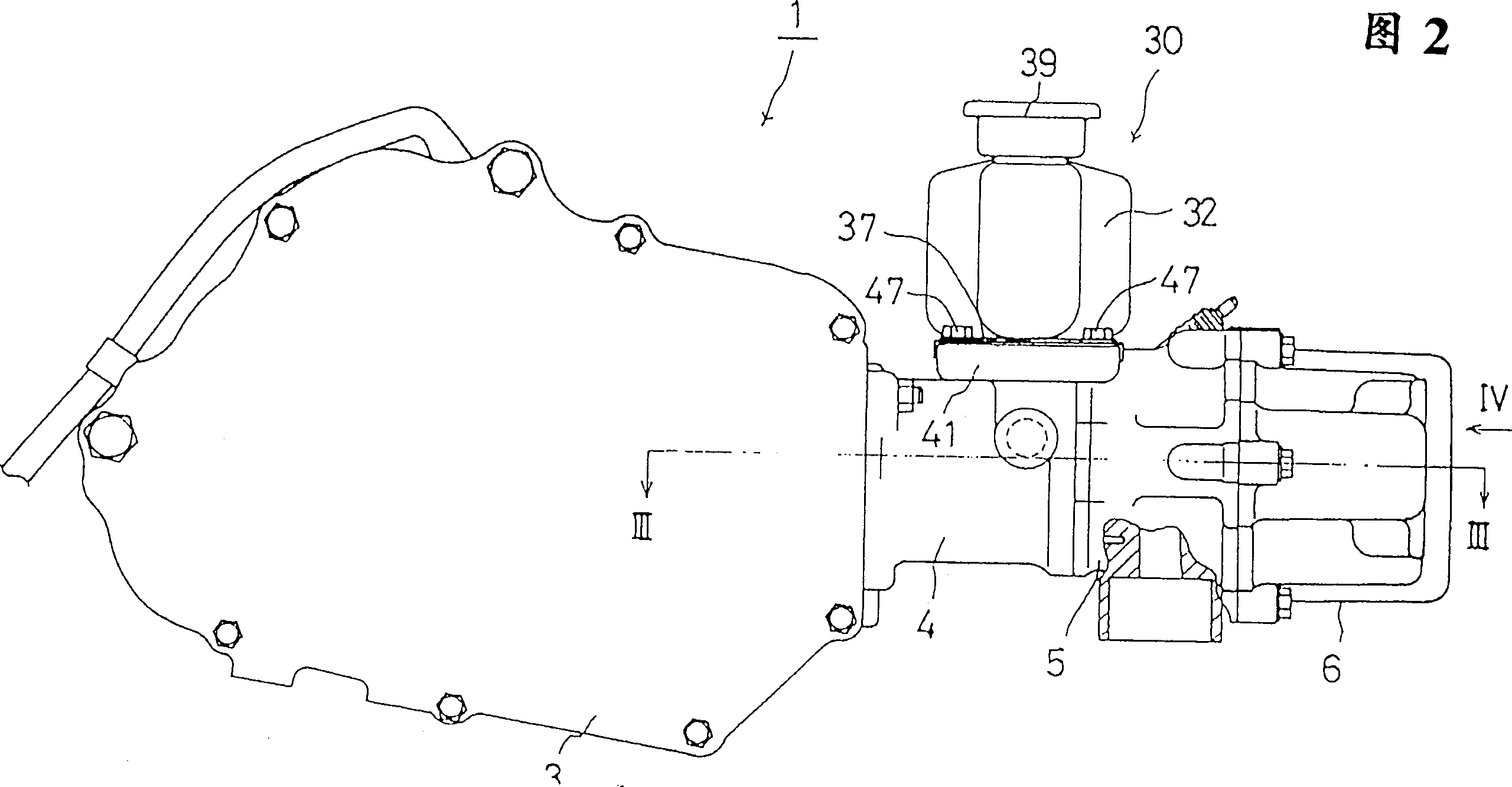
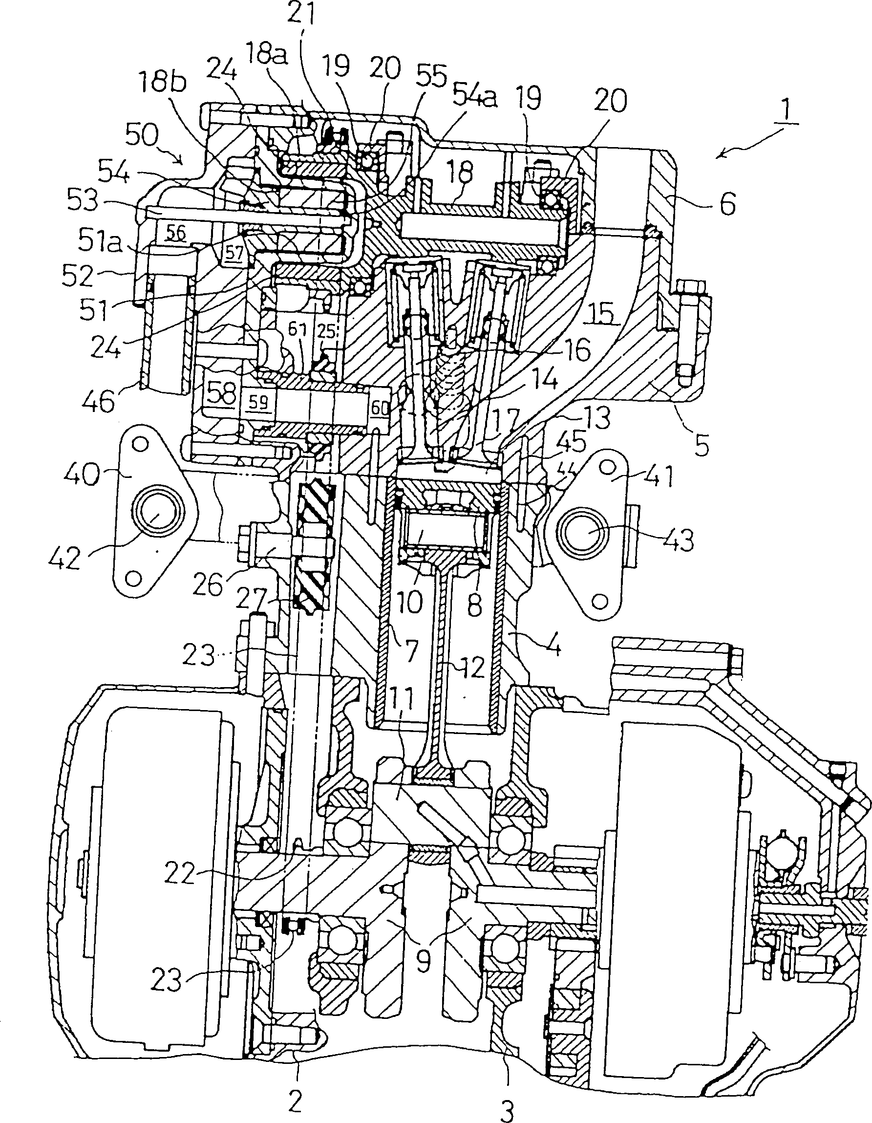
[0013] For implementing the inventions described in schemes 1 to 4 of the present invention, figure 1 The cooling device shown in FIG. 5 will be described.

[0014] figure 1 It is a schematic perspective view showing an embodiment of the present invention. An overhead valve type 4-stroke cycle (generally referred to as 4 cycle) single-cylinder type water-cooled internal combustion engine 1 is mounted between the front and rear wheels of a small motorized two-wheeled vehicle not shown in the figure. .

[0015] The water-cooled internal combustion engine 1 is composed of crankcases 2, 3, cylinder blocks 4, cylinder heads 5, and cylinder head covers 6 separated from the left and right. A cylinder block 4 is arranged at the front ends of the crankcases 2, 3. The cylinder bore of the cylinder block 4 The central axis of 7 is generally horizontally facing forward, and a cylinder head 5 and a cylinder head cover 6 are sequentially arranged in front of the cylinder block 4. These cr...


PUM


Abstract

This cooling device for a water cooling type internal combustion engine includes cooling water conduits 34, whose both ends are opened and which lead cooling water to the horizontal direction, and a pair of tanks 31, 32, which are mounted on the end of the cooling water conduits 34 and are mutually communicatable through the cooling water conduits 34, and has radiating fins 33, whose heat radiation surfaces face vertically crossing the cooling water conduits 34 in the longitudinal direction, are fitted to the cooling water conduits 34.

Description

technical field [0001] The present invention relates to a water-cooled internal combustion engine with a small displacement, and more particularly to a cooling device for a water-cooled internal combustion engine mounted on a small vehicle such as a motorcycle. Background technique [0002] Existing cooling device is commonly referred to as radiator, is used for cooling the cooling water that flows in the water-cooled internal combustion engine that two-wheeled motor vehicle is carried, and its structure has been described in No. 59-134777 Patent Publication of Real Opening. [0003] In the above-mentioned cooling device, a pair of water tanks are arranged up and down, and the two ends of the vertically opposite cooling water pipes are respectively inserted into the holes on the bottom wall of the upper water tank and the holes on the top wall of the lower water tank, and the upper and lower pair of water tanks are closed by the upper and lower water tanks. The cooling water...

Claims


Application Information

Patent Timeline
IPC IPC(8): B62J99/00F01P3/04F01P3/18F02B61/02
CPCF02B61/02
Inventor 冈野则明船山芳浩
Owner HONDA MOTOR CO LTD
Why Eureka
Try Eureka