Absorptive cooling for electronic devices

a technology of electronic components and absorptive coolers, which is applied in the direction of domestic cooling devices, lighting and heating apparatus, instruments, etc., can solve the problems of heat dissipation and increased heat flow away from electronic components, and achieve the effect of efficiently controlling heat and powering an absorptive cooler

Inactive Publication Date: 2008-07-01
OKEEFFE WILLIAM F
View PDF12 Cites 23 Cited by
  • Summary
  • Abstract
  • Description
  • Claims
  • Application Information

AI Technical Summary

Benefits of technology

[0011]In some embodiments, cowlings can be used to concentrate heat generated by components to more efficiently power an absorptive cooler. In other embodiments, a cowling can be used to thermally isolate components to be cooled from other components in the electrical device. In still further embodiments, insulating materials can be associated within a cowling to more efficiently control heat within an electronic device.

Problems solved by technology

In such embodiments, there can be a tendency for “negative feedback” such that as power consumption by the electronic device increases, the flow of heat away from the electronic component can increase to a degree greater than for simple passive heat dissipation.

Method used


Image

  • Absorptive cooling for electronic devices
  • Absorptive cooling for electronic devices
  • Absorptive cooling for electronic devices

Examples


embodiment 600

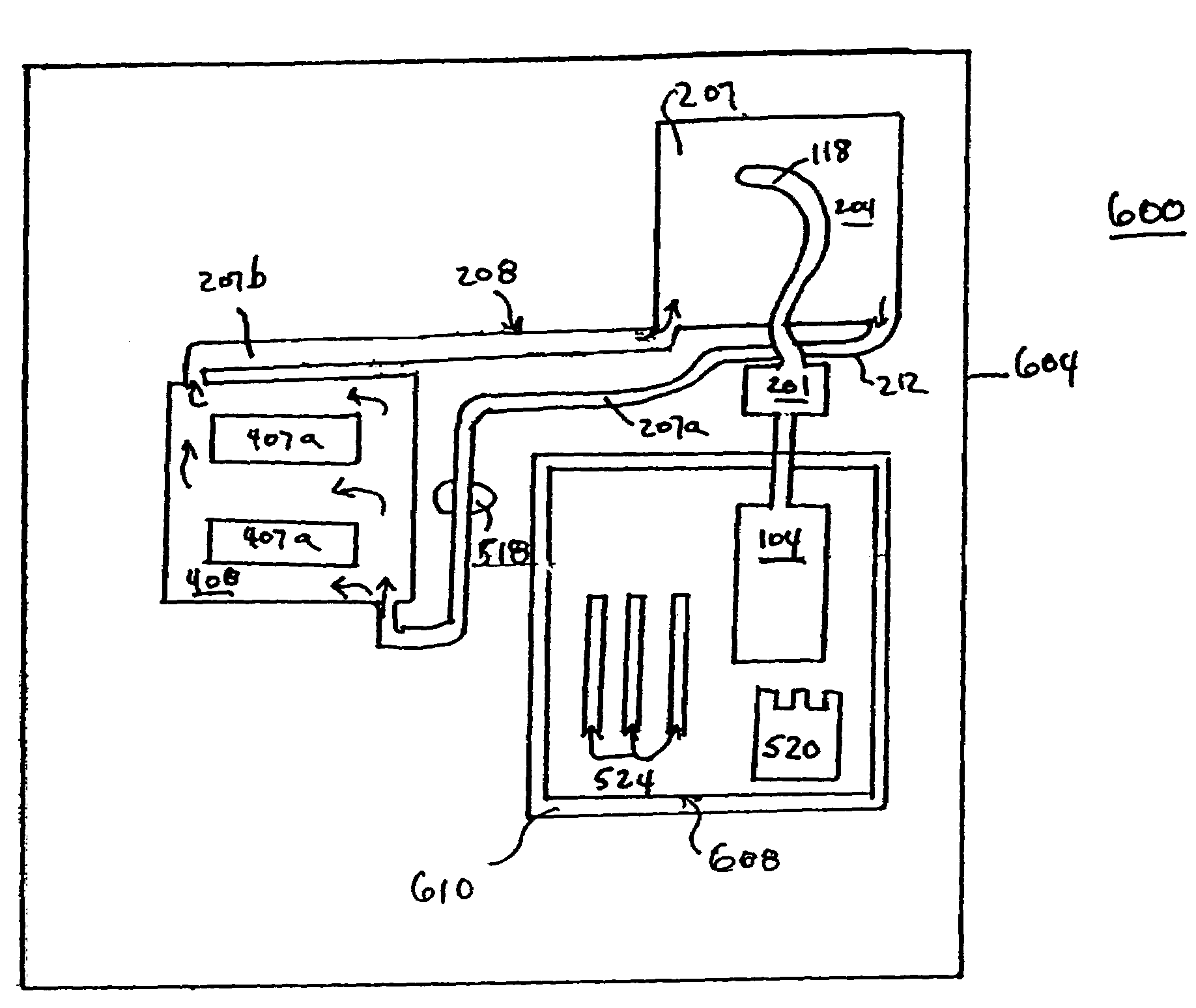
[0046]FIG. 6 depicts a schematic diagram of an alternative embodiment 600 of this invention, having shell 604 housing components of a system. Heat sources 520 and 524 and boiler 104 are housed within cowling 608. Most of the heat produced by sources 520 and 524 heat boiler 104, which is shown attached to the remainder of cooler 201 and evaporator 118 as in previous figures. As in FIG. 5, evaporator 118 is within a reservoir 204 containing heat exchange fluid 207, which circulates via pump 518 and tube 212 to electrical component 404. Cool heat exchange fluid 207a cools electrical component 408 containing devices 407a, thereby warming heat exchange fluid 207b, which is then carried back to compartment housing evaporator 118 via tube 208. Heat sources 520 and / or 524 may be transformers, circuit boards or other components that produce significant amounts of heat. Cowling 608 localizes heat produced by sources 520 and 524 to provide heat to boiler 104 and to avoid heating up other compo...

embodiment 700

[0047]FIG. 7 depicts a schematic diagram of another embodiment 700 of this invention. As in FIG. 5, heating elements 520 and 524 produce heat within shell 701. Motor 728 and fan 732 pull heated air 536 from within shell 701 past boiler 104, and then to outside shell 701, thereby powering absorptive cooler 201 with evaporator 118 within reservoir 204 containing heat exchange fluid 207. Heat exchange fluid 207 is pumped by pump 518 through tube 212 to electrical component 408 containing devices 407a. Cool heat exchange fluid 207a enters cowling 708 which houses electrical component 408 and cools component 408 and device 407a. Warm heat exchange fluid 207b exits cowling 708 and is returned via tube 208 to compartment housing evaporator 118 of absorptive cooling apparatus. If desired, insulating layer 710 can be applied to cowling 708, thereby keeping heat produced by elements 520 and 524 from electronic component 404.

embodiment 800

[0048]FIGS. 8a and 8b depict schematic drawings of embodiments of this invention. FIG. 8a depicts an embodiment 800 having a base 804 upon which device 814 is placed, thereby defining a space 820. Housing 818 is attached to base 804 as shown by the dashed line 824. Tube 812 carries cooled heat exchange fluid 207a into space 820, which is circulated (arrows) through space 820 by a pump (not shown). Heat produced by device 814 is transferred to heat exchange fluid 207a to produce warmed heat exchange fluid 207b, which is then carried by tube 808 back to the absorptive cooler (not shown).

[0049]FIG. 8b depicts an embodiment 801 similar to that shown above in FIG. 8a having flange 828 having fasteners 832 holding housing 818 to base 804, thereby permitting periodic removal of housing 808 to permit servicing or replacement of device 814.

[0050]It can be appreciated that in embodiments in which a heat exchange fluid comes into contact with a heat producing electrical element, such as 814 of...


PUM


Abstract

Embodiments of this invention include active electrical components withing a housing that contains an absorptive cooler. The absorptive cooler is used to cool active electrical components, such as central processors or other heat-sensitive components. In some embodiments, heat produced by electronic components can be used to provide heat to the absorptive cooler. By using heat generated from within the housing of the electronic device or other heat-producing element to drive an absorptive cooler, temperatures within heat-sensitive elements, such as a central processing unit can be reduced with a minimum of energy loss, and thereby permitting faster processing speed and reduced power consumption.

Description

PRIORITY CLAIM[0001]This application claims priority under 35 U.S.C. § 119(e) to U.S. Provisional Patent Application No. 60 / 659,302, filed Mar. 7, 2005, William O'Keeffe, Inventor, entitled “Absorptive Cooling for Electronic Devices,”. This application is expressly incorporated herein fully by reference.BACKGROUND[0002]1. Field of the Invention[0003]This invention relates to cooling devices for electronic components. Particularly, this invention relates to absorptive coolers and their use in electronic devices, such as computers. More particularly, this invention relates to devices and systems for keeping central processors and other active computer elements cool using heat generated by the electronic device.[0004]2. Description of the Art[0005]Electrical components that have active computational elements (e.g., computer processors, or “chips”) have become smaller over the decades since they were first introduced. As devices become smaller, the power consumption has been decreased, ...

Claims


Application Information

Patent Timeline
Patent Type & Authority Patents(United States)
IPC IPC(8): H05K7/20F28F7/00
CPCH05K7/20363G06F1/20F25B27/02F28D15/00G06F2200/201Y02A30/274
Inventor O'KEEFFE, WILLIAM F.
Owner OKEEFFE WILLIAM F
Why Eureka
Try Eureka