

Multi-layer inductance and capacitance composite element
一种电感电容、复合元件的技术,应用在多层LC复合元件领域,能够解决增加插入损耗等问题
- Summary
- Abstract
- Description
- Claims
- Application Information
AI Technical Summary
Problems solved by technology
Method used
Image

Examples
no. 1 example
[0027] (first embodiment: Figures 1 to 5 )
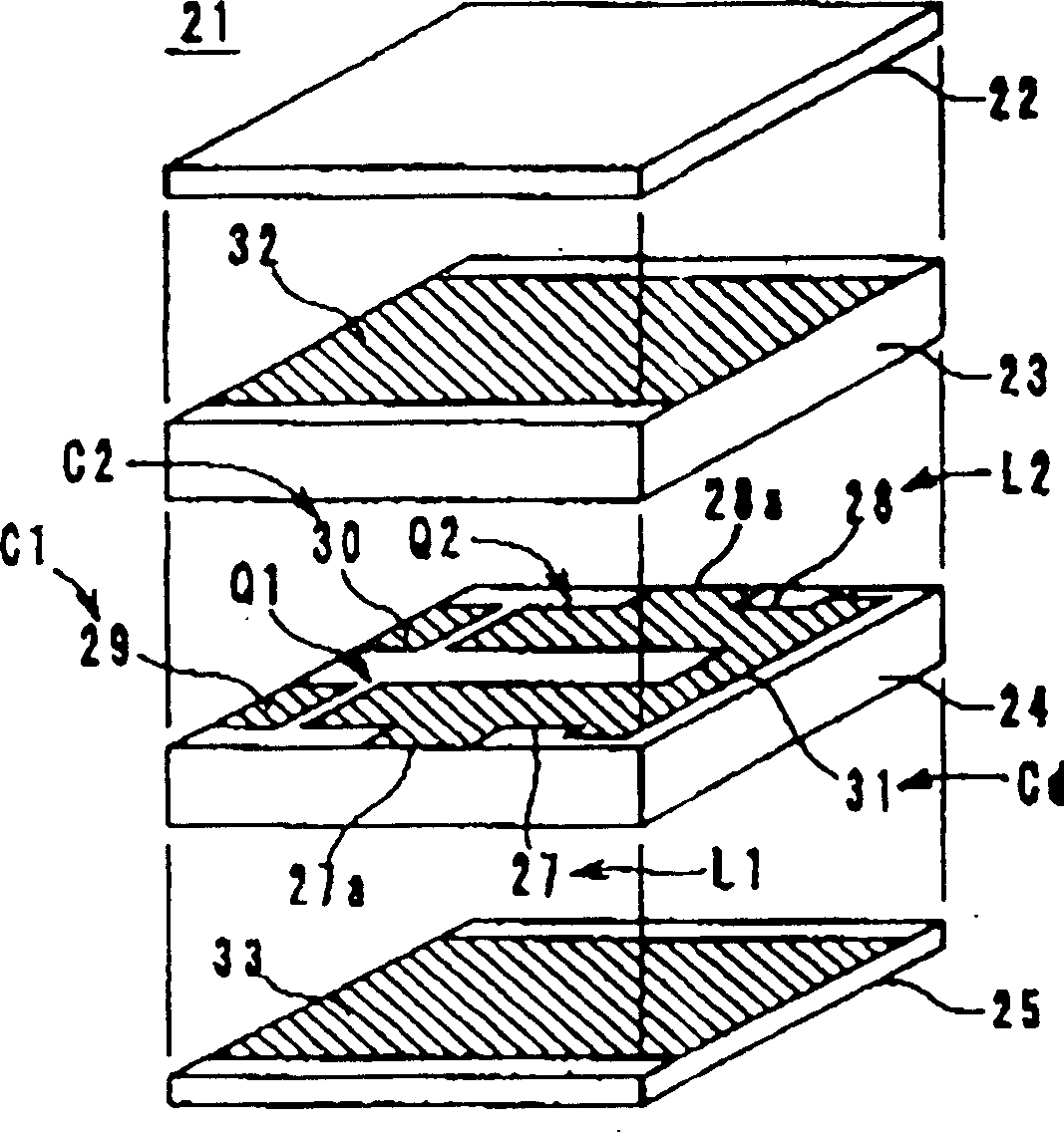
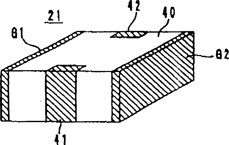
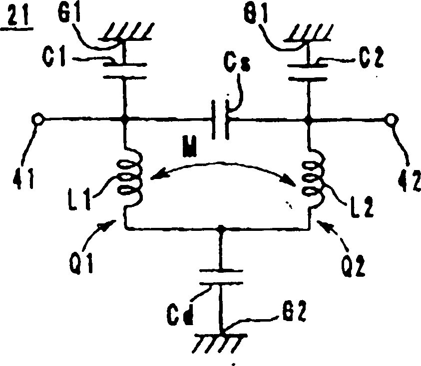
[0028] figure 1 The structure of the multilayer LC composite filter 21 is shown. figure 2 a perspective view showing the appearance of the LC filter 21, and image 3 Its equivalent circuit diagram is shown. LC filter 21 is a two-stage filter having LC resonators Q1 and Q2.
[0029] Such as figure 1 As shown in , the multilayer LC filter 21 includes: an insulating sheet 24 formed with inductance patterns 27 and 28, frequency adjustment capacitor patterns 29 and 30, and a connection pattern 31; an insulating sheet 23 formed with a shielding pattern 32; 33 insulating sheet; and insulating sheet 22 and so on. The insulating sheets 22 to 25 are sheets formed by mixing dielectric powder and magnetic powder with a binder and the like. The patterns 27 to 33 are formed of materials such as silver, platinum, copper, nickel, gold, silver-platinum, etc., and the patterns are formed on the insulating sheet by printing or other methods...
no. 2 example
[0038] (second embodiment: Figure 6 and 7 )
[0039] Such as Figure 6 As shown in , the multilayer LC filter 50 includes: an insulating sheet 53 formed with frequency adjustment capacitor patterns 60 to 62 , an insulating sheet 54 formed with inductor patterns 57 , 58 and 59 and a connection pattern 63 , an insulating sheet 54 formed with a capacitor pattern 64 The insulating sheet 55, the insulating sheets 52 and 56 formed with the shielding patterns 65 and 66, respectively, and the like.
[0040] The linear inductor patterns 57 to 59 having a predetermined pattern width are arranged parallel to each other from the left side to the right side of the insulating sheet 54 . One end of each of the inductance patterns 57 to 59 is connected to the connection pattern 63, is short-circuited with each other, and their other ends are open-circuited. The inductor patterns 57, 58, and 59 form inductors L1, L2, and L3, respectively. The axes of the inductors L1 to L3 are parallel i...
no. 3 example
[0048] (the third embodiment: Figures 8 to 12 )
[0049] Such as Figure 8 As shown in , the multilayer LC filter 81 includes insulating sheets 82 to 89 on which inductor via holes 90a to 90d, 91a to 91d and 92a to 92d, capacitance patterns 93 to 95, frequency adjustment circuit patterns 96 to 98 are formed. , coupling capacitor patterns 99 to 101, connection pattern 102, shielding patterns 105 and 106, and the like.
[0050] Inductor via holes 90a to 90d, 91a to 91d, and 92a to 92d are linked in the direction in which the insulating sheets 84 to 87 are laminated to constitute columnar inductors L1, L2, and L3. The axial directions of the inductors L1 to L3 are perpendicular to the surfaces of the sheets 84 to 87 . One end of each of the inductors L1 to L3, that is, the via holes 90d, 91d, and 92d connected to the connection pattern 102, is short-circuited.
[0051] The frequency adjustment circuit patterns 96, 97, and 98 are opposed to the shield pattern 105 via the insu...
PUM
 Abstract
Description
Claims
Application Information