
Optical disk device

A kind of optical disc device and optical disc technology, which is applied in the direction of light beam source, optical recording head, optical erasing system, etc., and can solve the problems such as the change of difference signal

Inactive Publication Date: 2004-06-30
TEAC CORP
View PDF0 Cites 0 Cited by
  • Summary
  • Abstract
  • Description
  • Claims
  • Application Information

AI Technical Summary

Problems solved by technology

[0018] The above formula still expresses the difference signal correction offset voltage Vossub has a gain value G in the formula, so the difference signal correction offset voltage value has the problem of changing with the switching of the gain value G

Method used


Image

  • Optical disk device
  • Optical disk device
  • Optical disk device

Examples


Embodiment Construction

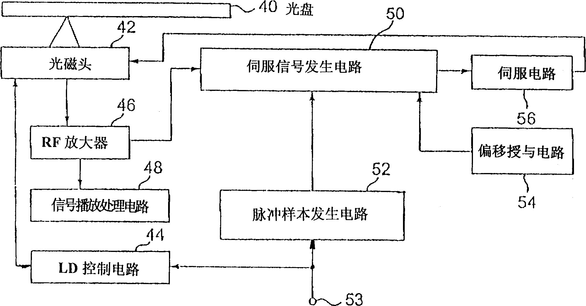
[0050] figure 1It is a block diagram of an embodiment of the optical disc device of the present invention, in which a recordable optical disc 40 such as CD-R or CD-RW is driven to rotate at a prescribed speed by a spindle motor (not shown). The optical head (pick-up) 42 is moved along the radial direction of the optical disc by a thread motor (not shown in the figure). The optical magnetic head 42 consists of an optical objective lens, a starter, a 1 / 4 wavelength plate, a collimator mirror (collimotorleris), a beam splitter (beam splitter), a light emitting component (laser diode laser diode), a front monitor (front monitor) and a photodetector and so on.

[0051] The LD control circuit 44 uses the read power when playing, and uses the erasing power according to the recording pulse when recording. The writing power or the reading power makes the laser diode in the optical magnetic head 42 emit light to output a laser beam (beam). The LD control circuit 44 detects the inten...


PUM


Abstract

Disclosed is an optical disc device with not necessary to change the correction offset voltages even though the gain of the amplifier is changed. The optical disc device comprises the following elements. A photo detecting device divided into a plurality of photo detectors is used for detecting the reflected light beams illuminated on an optical disc. A plurality of amplifiers is used for changing gains to respectively amplify the output signals of the photo detectors when recording and reproducing on / from the optical disc. A calculating device is used for calculating the output signals of the amplifiers to generate the servo signals. By adding the correction offset signals for correcting the offset voltages of the amplifiers and the photo detectors to the amplifiers, the correction offset signals are amplified. It is, therefore, not necessary to change the correction offset voltages for the gain-switching of the amplifier.

Description

technical field [0001] The invention relates to an optical disc device, in particular to an optical disc device for recording information on an erasable optical disc. Background technique [0002] There are write-once (Write Once) and erasable (Erasable) types of recordable optical discs. Write-once optical discs such as CD-R (compact Disk Recordable) or erasable optical discs CD-RW (compact Disk Rewritable) and DVD-RW (Digital Versatile Disk Rewritable) are provided with a pregroove for guiding. The center frequency of the pregroove is 22.05KHZ, which only snakes in the radial direction, also known as the address information of ATID (Absolute time In Pregroove) recording, and there are multiple records according to FSK modulation with a maximum deviation of ±1KHZ. [0003] The tracking and focus servo circuit of the optical disc device for recording and playing of this type of recording optical disc uses multiple photodetectors to detect the reflected light of the optical ...

Claims


Application Information

Patent Timeline
Patent Type & Authority Patents(China)
IPC IPC(8): G11B7/0055G11B7/09G11B7/125G11B7/126
CPCG11B7/094G11B7/0908G11B7/0941G11B7/0901G11B7/0943G11B7/126G11B7/0055
Inventor 真下著明高坂纪一
Owner TEAC CORP
Features
  • Generate Ideas
  • Intellectual Property
  • Life Sciences
  • Materials
  • Tech Scout
  • Unparalleled Data Quality
  • Higher Quality Content
  • 60% Fewer Hallucinations
Learn More