Evaporator system

A technology of evaporator and refrigeration capacity, applied in the direction of evaporator/condenser, household refrigeration device, cooler, etc., can solve the problems of large number of parts, expensive welding device, high installation cost, achieve precise location and avoid refrigeration loss. Effect

Inactive Publication Date: 2004-07-14
BSH BOSCH & SIEMENS HAUSGERAETE GMBH
View PDF0 Cites 1 Cited by
  • Summary
  • Abstract
  • Description
  • Claims
  • Application Information

AI Technical Summary

Problems solved by technology

Such an upstream connection of the evaporator plate used as a cold room evaporator with so-called tube evaporators used in the freezer, in addition to the large number of parts, also results in the necessity of combining different materials within cost and production conditions. Liquid-tight and gas-tight interconnection, whereby special welding methods must be used, such as a special form of resistance welding, for which appropriate welding devices are rather expensive
In addition, the installation costs of such evaporator installations are relatively high due to the large number of individually joined joints, wherein high demands are also placed on the quality and precision of the workman's workmanship in order to ensure a liquid-tight and gas-tight production of the joints

Method used


Image

  • Evaporator system
  • Evaporator system
  • Evaporator system

Examples


Embodiment Construction

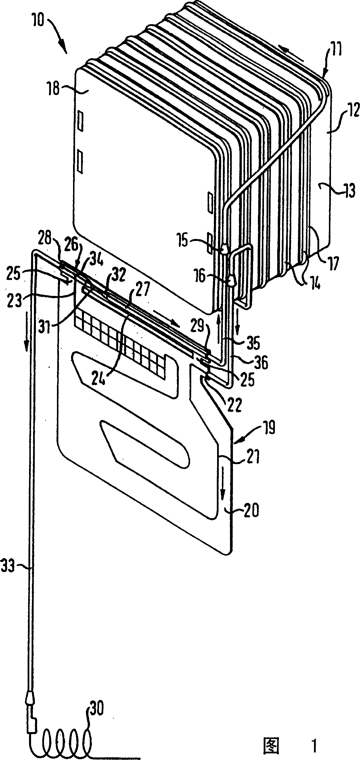
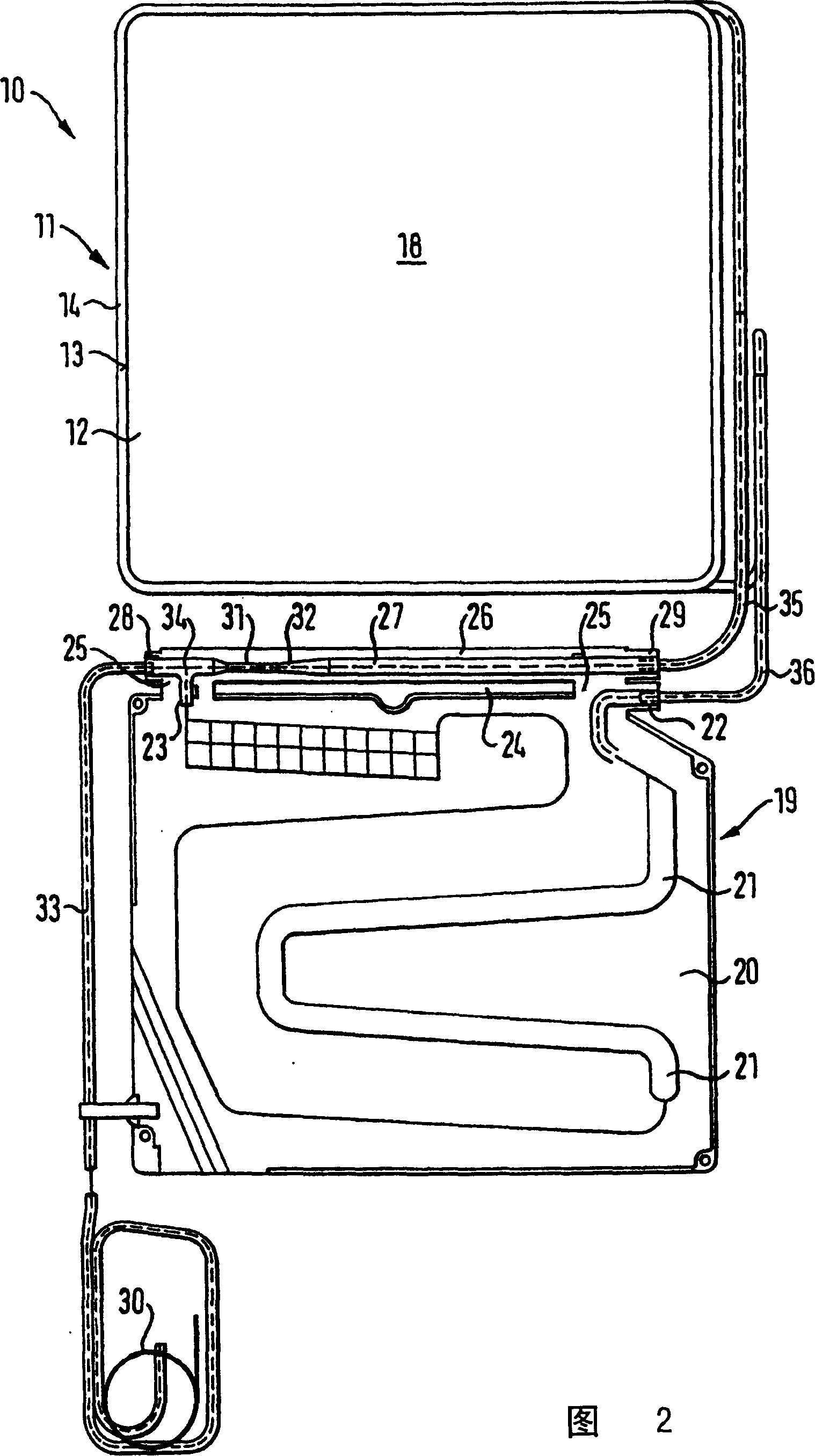
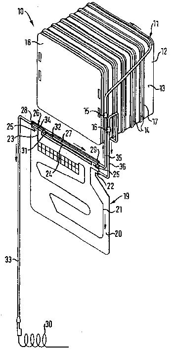
[0021] FIG. 1 shows in a simplified schematic diagram an evaporator arrangement 10 with a freezer evaporator 11 having a carrier tube 12, for example made of aluminum sheet, in the direction of the refrigerating appliance insulation. The installation surface 13 of the installation surface 13 is provided with a pipeline 14 for guiding the refrigerant, which is made of an aluminum tube and has a connector 15 or 16 at its two ends, and the aluminum tube is in thermal contact with it on the installation surface 13. In order to increase the heat transfer surface of the pipes 14 on the mounting surface 13 , the former is provided on its free surface with an aluminum-covered adhesive tape which is fastened to the mounting surface 13 of the carrier tube 12 . The carrier tube 12 is equipped on its rear side with a rear wall 18 made of aluminum sheet, which together with the carrier tube 12 and the pipes 14 wound on the carrier tube form a freezer compartment evaporator 11 known as a so-...


PUM


Abstract

The invention relates to an evaporator system (10) having at least two evaporators actuated by means of a condenser with coolant which is delivered via an injection position (32). Said evaporators have differing refrigerating capacities and are arranged one behind the other such that they are connected in series. The evaporator having a lower refrigerating capacity (19) is constructed in a plate-like manner, whereas the evaporator having a higher refrigerating capacity (11) is provided with a conduit (14) for guiding the coolant and is connected in series before the evaporator having a lower refrigerating capacity (19). The plate-like evaporator having a lower refrigerating capacity (19) has a section (26) which is provided with the injection position (32) for the coolant and which is at least thermally decoupled to the greatest possible extent from the rest of the plate surface (20) of the evaporator (19).

Description

technical field [0001] The invention relates to an evaporator device with at least two evaporators of different refrigerating capacity installed in series one behind the other and supplied with refrigerant by a condenser through an injection point, wherein the evaporator with the lower refrigerating capacity is made as a plate shape, while the evaporator with higher cooling capacity is equipped with a pipe for guiding the refrigerant, and the evaporator with lower cooling capacity is connected in series in front. Background technique [0002] For combined refrigeration and freezing, so-called box evaporators are used in the prior art to cool the freezer compartment. Such evaporators have a carrier plate bent into a right-angled tube, which is wound with refrigerant-conducting lines on its mounting surface. In order to simplify the processing and take into account heat conduction and cost reasons, the carrier plate and the pipeline are made of aluminum, a tube insert is prov...

Claims


Application Information

Patent Timeline
Patent Type & Authority Patents(China)
IPC IPC(8): F25B39/02F25B41/37F25D11/02
CPCF25B39/024
Inventor D·西斯利克
Owner BSH BOSCH & SIEMENS HAUSGERAETE GMBH
Why Eureka
Try Eureka