Liquid crystal display device
A liquid crystal display and device technology, which is applied in the field of so-called partial transmission active matrix liquid crystal display devices, and can solve problems such as insufficient efficiency
- Summary
- Abstract
- Description
- Claims
- Application Information
AI Technical Summary
Problems solved by technology
Method used
Image
Examples
Embodiment 1
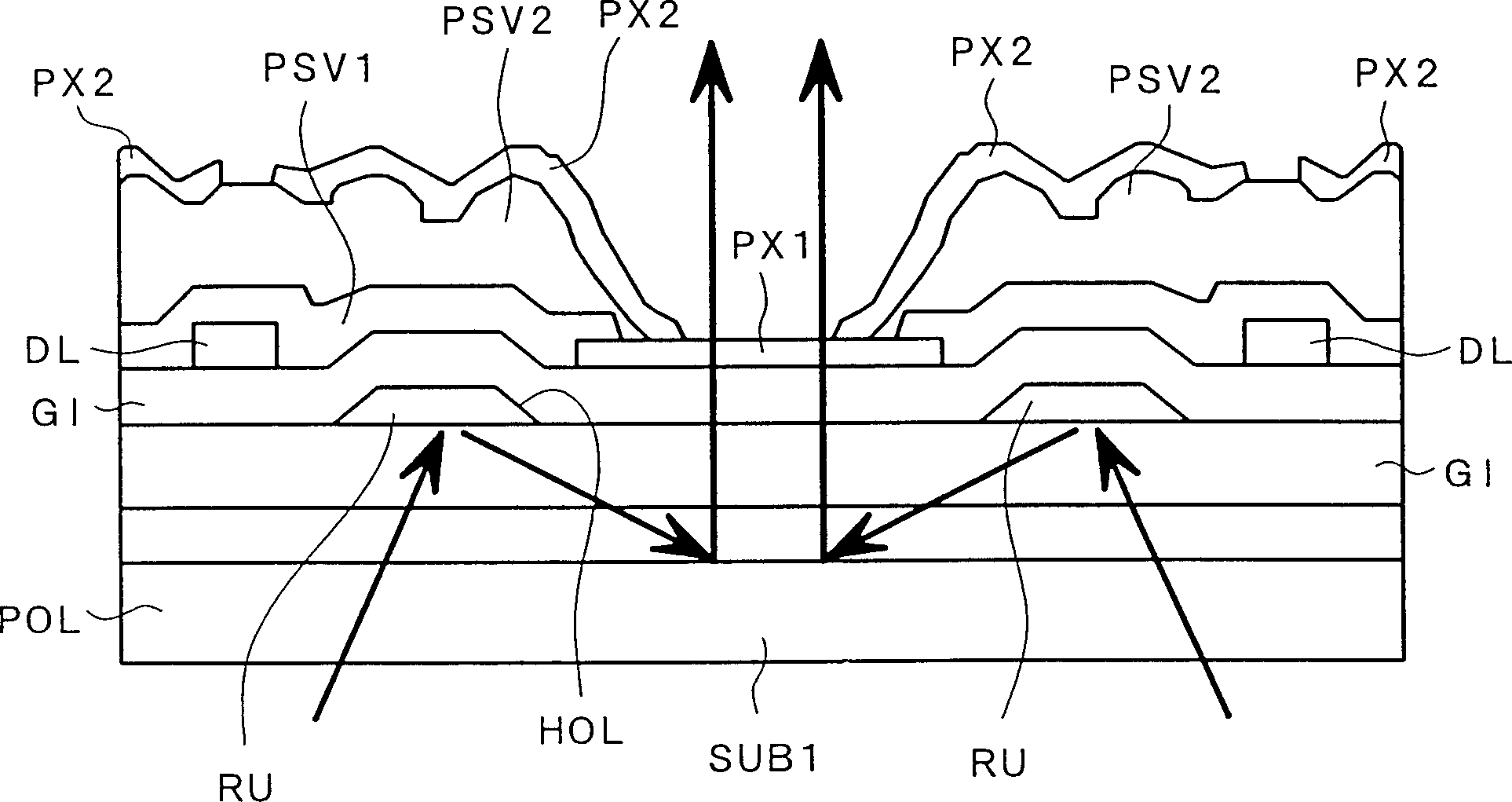
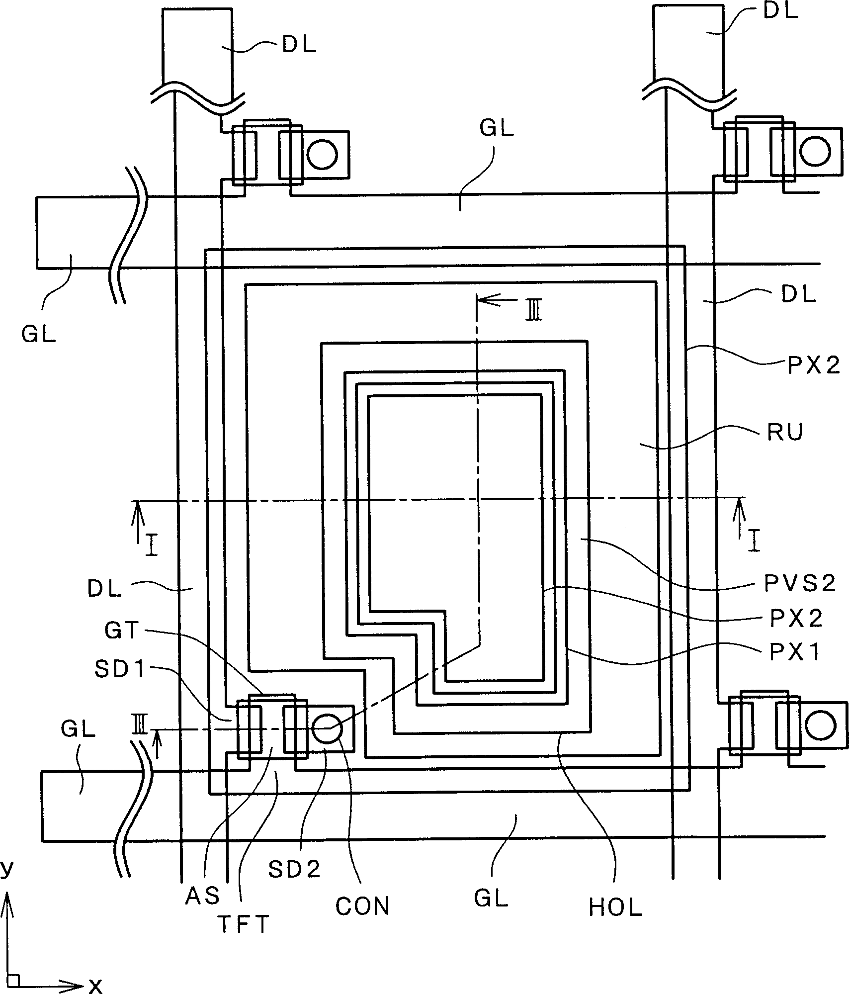
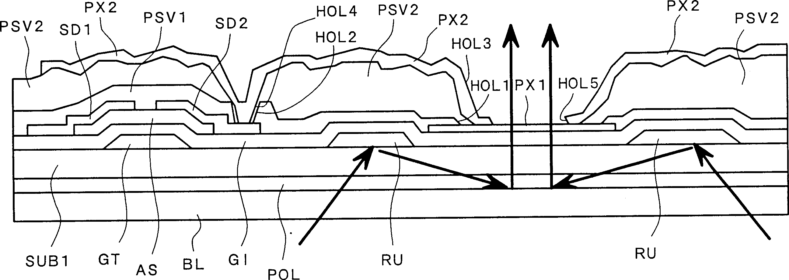
[0034] figure 2 It is a plan view of a pixel structure of a liquid crystal display device according to an embodiment of the present invention. also, figure 1 shows along the figure 2 Pixel cross-sectional view of midline I-I; image 3 shows along the figure 2 Pixel cross-sectional view of midline III-III.
[0035] figure 2 shows a plan view of a single pixel among the pixels arranged in a matrix, and the other pixels located around or above and below the pixel are similar in structure to the pixel shown.
[0036] exist figure 2 In this method, gate signal lines GL are first arranged on the surface of a transparent substrate SUB1 so that these lines extend along the "x" direction in the figure and are parallel to each other in the "y" direction.
[0037] As will be explained later, a region surrounded by these gate signal lines and drain signal lines extending along the “y” direction in the figure and parallel to each other in the “x” direction is defined as a pixel...
Embodiment 2
[0070] Figure 4 is a plan view of a pixel structure of a liquid crystal display device according to another embodiment of the present invention, corresponding to figure 2 . also, Figure 5 for along Figure 4 See the cross-sectional view of the pixel on the midline V-V, while Image 6 for along Figure 4 Cross-sectional view of midline VI-VI.
[0071] and figure 2 The difference in the structure shown in is that the light reuse film RU is integrated with the light reuse film RU in the adjacent pixel area along the x direction in the figure (ie along the extension direction of the gate signal line GL).
[0072] More specifically, the light reuse film RU extends to the bottom portion of the drain signal line DL.
[0073] As mentioned above, the drain signal line DL is made of the same material as the drain SD1 and source SD2 of the thin-film transistor TFT, and they are all made of continuously pressed or "multi-layered" high-melting-point metals (Mo, Ti, Ta, Cr) and ...
Embodiment 3
[0083] Figure 7 It is a plan view of a pixel structure of a liquid crystal display device according to yet another embodiment of the present invention, corresponding to Figure 5 . in addition, Figure 8 for along Figure 7 Cross-sectional view of midline VIII-VIII.
[0084] Figure 7 The embodiment shown in the structure of embodiment 2 has been further improved. The main difference from Embodiment 2 is that the light reuse film RU is physically divided into fragments, and these fragments form many mutually separated light reuse films RU1 on the same layer (the upper surface of the electrically insulating film GI).
[0085]The reason for adopting such a split structure of the light reuse film RU1 is as follows: When one drain signal line DL is electrically short-circuited with the light reuse film RU1 below it for some reason, The capacitive coupling between RU1 and the pixel electrode PX causes a change or deviation of the potential on the pixel electrode PX, and an o...
PUM
 Abstract
Description
Claims
Application Information
 - R&D
- Intellectual Property
- Life Sciences
- Materials
- Tech Scout
- Unparalleled Data Quality
- Higher Quality Content
- 60% Fewer Hallucinations
Browse by: Latest US Patents, China's latest patents, Technical Efficacy Thesaurus, Application Domain, Technology Topic, Popular Technical Reports.
© 2025 PatSnap. All rights reserved.Legal|Privacy policy|Modern Slavery Act Transparency Statement|Sitemap|About US| Contact US: help@patsnap.com


