
Piezoelectric vibrator

A piezoelectric vibrator and vibrator technology, applied in electrical components, impedance networks, etc., can solve the problems of limited miniaturization of the vibrator, gaps and cracks at the end of the vibrator, and increasing the length of the electrodeless part.

Inactive Publication Date: 2004-08-18
PANASONIC CORP
View PDF1 Cites 0 Cited by
  • Summary
  • Abstract
  • Description
  • Claims
  • Application Information

AI Technical Summary

Problems solved by technology

[0008] In order to fully limit the vibration energy and reduce the vibration displacement at the end of the vibrator, the length of the electrodeless part must be increased. Therefore, in the case of fully ensuring the attenuation of the vibration displacement at the end of the vibrator, the small size of the vibrator is limited
[0009] In addition, as the technical solution proposed in US Patent No. 5,548,178, by processing the section of the vibrator into a bevel shape or a convex shape, the attenuation of the vibration displacement at the end of the vibrator is larger than that when the section of the vibrator is rectangular, so the vibrator can be reduced. However, because the thickness of the end of the vibrator becomes smaller, there are gaps and cracks at the end of the vibrator, the mechanical strength is poor, and it is difficult to perform stable installation
[0010] Furthermore, in a vibrator whose main vibration is thickness shear vibration, if the vibrator part and the support part are integrated at the end of the vibrator in the longitudinal direction and the slit is provided at the end of the vibrator in the width direction, there may be a problem due to the The problem that there is a large difference in characteristics due to processing accuracy such as the presence or absence of chips and surface roughness

Method used


Image

  • Piezoelectric vibrator
  • Piezoelectric vibrator
  • Piezoelectric vibrator

Examples


Embodiment Construction

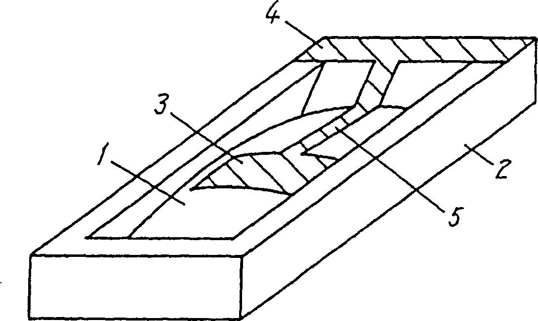
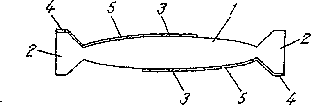
[0042] Refer to the following figure 1 , figure 2 , Figure 4-Figure 9 , an embodiment of the present invention will be described. exist figure 1 Among them, 1 is a piezoelectric vibrator, 2 is a supporting part integrated with the vibrator 1, 3 is an electrode for excitation provided opposite to the front and back of the vibrator 1, 4 is an electrode for external connection, and 5 is for external lead-out electrode.

[0043] As an example, consider a vibrator using a lithium tantalate single crystal X plate, in which thickness shear vibration is the main vibration. Now if it is considered that the resonant frequency of the vibrator is 20 MHz, the thickness H of the vibrator is about 100 μm. In a conventional design example, since L / H is set to 14 or more, assuming that L / H is equal to 14, the length L of the vibrator in the longitudinal direction when H is about 100 μm is about 1.4 mm. Calculate the attenuation degree of the vibration displacement at this time. The a...


PUM


Abstract

A piezoelectric vibrator using thickness mode as the primary vibration and having a cross section of a bevel or convex configuration is provided. By employing a structure in which a vibrator 1 and a support section 2 are composed of the same material, the end portions of the vibrator section are integrated, and the configuration of the cross section of the vibrator 1 is such that the thicknesses of the end portions of the vibrator are smaller than that of the central portion of the vibrator, a superior mechanical strength without chipping or cracking at the end portions of the vibrator is obtained allowing easy mounting while keeping the vibrator size small. The structure provides an added effect of a small dispersion of characteristic because the end portions of the vibrator are not exposed and the dispersion of the precision of working such as chipping and surface roughness at the end portions of the vibrator is small.

Description

technical field [0001] The present invention relates to a piezoelectric vibrator having a thickness mode as a main vibration processed into a slope shape and a convex shape. Background technique [0002] Piezoelectric vibrators have long been used as clock pulse sources for various electronic devices, etc., but most of them are small in shape, especially flat-mounted piezoelectric vibrators often use thin rectangular ones. Among the oscillators used in clock pulse sources, etc., as vibration elements, stable temperature characteristics and high mechanical quality factor Q are required, so that at a certain temperature, the vibration frequency will not be affected by the main vibration (often thickness shear). Thickness modes such as vibrations, thickness longitudinal vibrations) are coupled with unwanted vibrations (also referred to as spurious vibrations) to undergo rapid changes. [0003] For example, a piezoelectric vibrator using an AT-cut crystal plate and an X-plate o...

Claims


Application Information

Patent Timeline
Patent Type & Authority Patents(China)
IPC IPC(8): H03H9/19H03H9/05H03H9/17
CPCH03H9/132H03H9/0595H03H9/177H03H9/02133H03H9/19
Inventor 佐佐木幸纪岛村彻郎
Owner PANASONIC CORP
Learn More