Combustion chamber unit of gas turbine
A technology of gas turbines and combustion chambers, which is applied in the direction of gas turbine devices, combustion chambers, continuous combustion chambers, etc., and can solve limited, difficult, and difficult problems
- Summary
- Abstract
- Description
- Claims
- Application Information
AI Technical Summary
Problems solved by technology
Method used
Image

Examples
Embodiment Construction
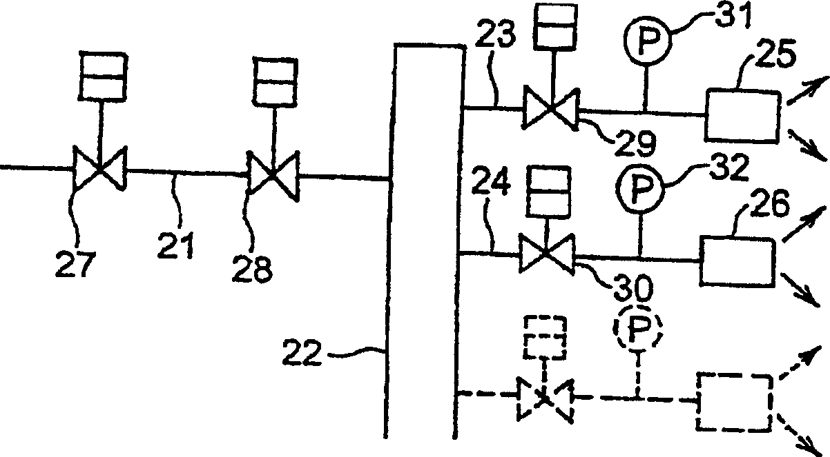
[0030] Below, according to figure 1 The embodiment shown in is a more specific description of the gas turbine combustor arrangement of the present invention. It should be pointed out that although multiple fuel supply systems are proposed, only two of them are taken as representatives for illustration. exist figure 1In , reference numeral 21 denotes a fuel supply pipe, and the structure of this system is such that fuel guided through the fuel supply pipe 21 enters fuel supply systems 23 , 24 through a manifold 22 and is supplied to each combustion chamber 25 , 26 . A pressure control valve 27 and a flow control valve 28 are provided in the fuel supply pipe 21 . Also, flow control valves 29, 30 and pressure gauges 31, 32 are located in the fuel supply systems 23, 24 connected to the combustion chambers 25, 26, respectively.
[0031] Here, the structure of the entire system is made such that the flow control valves 29, 30 respectively provided in the fuel supply systems 23,...
PUM
 Abstract
Description
Claims
Application Information
 - R&D
- Intellectual Property
- Life Sciences
- Materials
- Tech Scout
- Unparalleled Data Quality
- Higher Quality Content
- 60% Fewer Hallucinations
Browse by: Latest US Patents, China's latest patents, Technical Efficacy Thesaurus, Application Domain, Technology Topic, Popular Technical Reports.
© 2025 PatSnap. All rights reserved.Legal|Privacy policy|Modern Slavery Act Transparency Statement|Sitemap|About US| Contact US: help@patsnap.com