Mixing/charging port for medical treatment

A technology for medical use and co-injection, applied in other medical devices and other directions, can solve the problems of rising cost, complex structure, easy to be polluted and so on

Inactive Publication Date: 2004-11-03
JMS CO LTD
View PDF0 Cites 0 Cited by
  • Summary
  • Abstract
  • Description
  • Claims
  • Application Information

AI Technical Summary

Problems solved by technology

That is, first, the depth of the quasi-needle receiving part of the mixing port should be deepened, and this shape is not easy to remove the liquid leaked from the valve, and it is easy to be contaminated
Also, in the mixed injection port where the dummy needle receiving part is deep, mixed injection may start when the dummy needle is not fully inserted into the valve.
In this case, the volume of the mixed injection is reduced and an effective dose of the drug cannot be injected
Second, the structure of the valve is complicated, resulting in an increase in cost
And the more complex the structure, the more likely the valve will fail
[0005] On the other hand, it is difficult to insert the pseudo-needle of the syringe into the mixed injection port in the conventional simple (for example, a valve provided with only a slit on the disc-shaped elastic member), and even if it can be inserted, it is difficult to insert it. Difficulty keeping the syringe securely on the mixing port
This is because, conventionally, disc-shaped valves are made of a material with relatively high elasticity, and have a simple structure with only notches formed on the thicker body, so the resistance when inserted is large, and the deformation of the valve during retention is also small. big sake
In addition, if the wall thickness of the elastic member in the valve is reduced or a material with low elasticity is used to reduce the resistance during insertion, the check effect of the valve will be reduced, and liquid leakage may occur.

Method used


Image

  • Mixing/charging port for medical treatment
  • Mixing/charging port for medical treatment
  • Mixing/charging port for medical treatment

Examples


Embodiment Construction

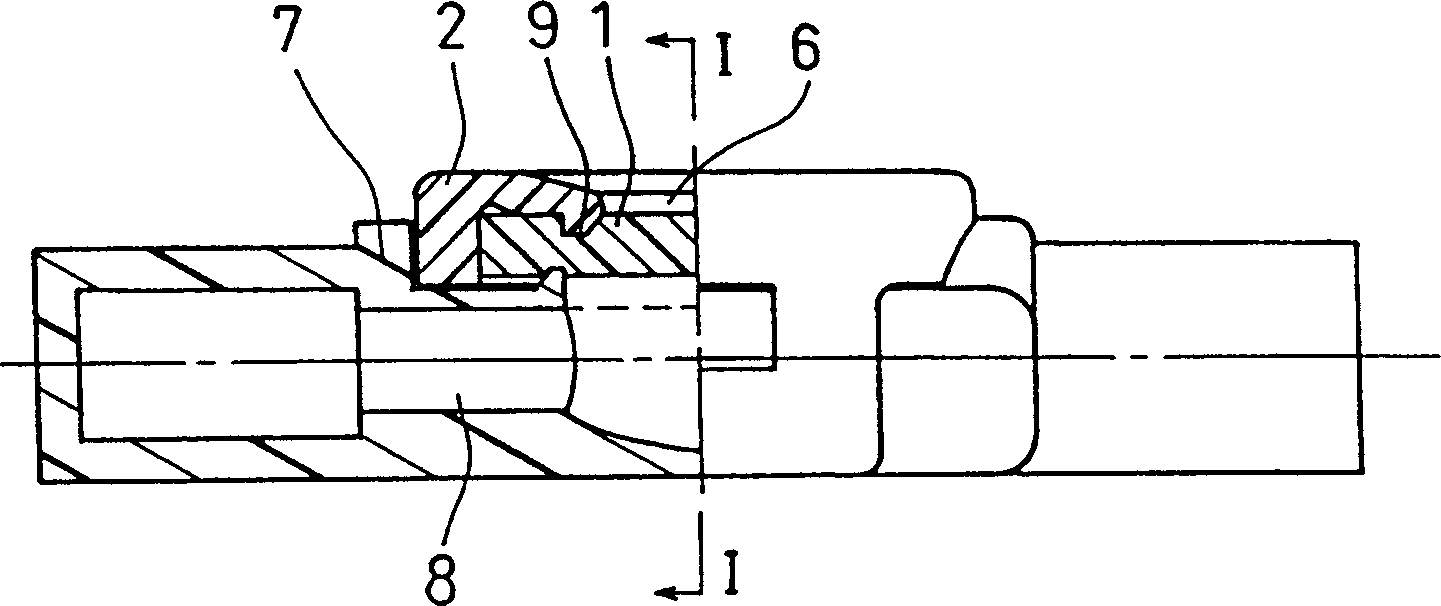
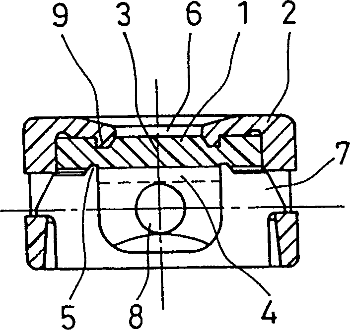
[0047] The mixed injection port for medical use of the present invention is mainly composed of a valve for opening and closing the flow path, a cap for holding the valve, and an insert locking mechanism formed on the cap. Hereinafter, respective constituent requirements will be described.

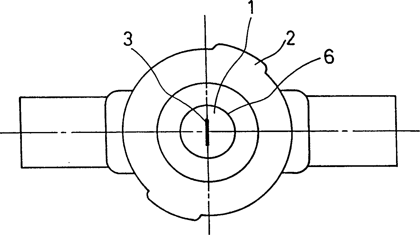
[0048] First, the cap is not particularly limited in its form as long as it can firmly hold (hold) the valve when it is inserted into or pulled out from the valve. For example, if Figure 1B As shown, when the cap 2 covering at least the upper peripheral portion of the valve 1 is formed except for the central portion (open) of the front side of the valve 1, it is easy to observe the insertion site of the quasi-needle, and it is possible to prevent accidental contact from occurring. contamination of the valve surface. It is more effective by providing a taper (inclination) of a gentle slope on the front side of the cap 2 . Furthermore, the lower side of the cap 2 or the valve 1 preferably...


PUM


Abstract

A mixing / charging port for medical treatment capable of reliably mixing / charging solutions or collecting the solutions in a medical instrument equipped with a solution feed passage, comprising a disc-like valve (1) having an insertion hole at the center, a cover (2) for restraining the valve (1) by covering at least the upper part of the periphery of the valve (1) with the center on the front surface side of the valve (1) left uncovered, and a round fitting hole (6) formed at the center of the cover (2) as anchor means for anchoring an insertion member to a mixing / charging port, the fitting hole (6) and the insertion member being so fitted to each other as to be capable of anchoring.

Description

technical field [0001] The present invention relates to a medical mixing port installed in a medical device for performing mixed injection of liquid from the outside of the liquid delivery path, or conversely drawing liquid from the inside of the liquid delivery path, for easy and reliable operation. Background technique [0002] In order to inject different kinds of medicinal liquids mixedly during infusion or blood transfusion for patients, or to sample the liquid flowing in the liquid delivery path, it is often necessary to set a side injection line in the main liquid delivery path. At this time, conventionally, a mixed injection port (stopper) for puncturing made of rubber is provided in the liquid delivery path of the infusion device, and an injection needle or the like is punctured through the mixed injection port for mixed injection. However, in the conventional method, when the needle is punctured from other than the puncture site specified in...

Claims


Application Information

Patent Timeline
Patent Type & Authority Patents(China)
IPC IPC(8): A61M39/00A61M39/02A61M39/04
CPCA61M39/02A61M39/045
Inventor 山中修一冲山忠藤井亮至
Owner JMS CO LTD
Why Eureka
Try Eureka